Screen Elements, Lines, and Labeling
There are many areas of designing a system file where labeling and drawing lines is essential. The size and shape of the Layout may be changed and Toolbars hidden to customize the appearance of the software.
Workspace Layout
The Layout has fixed dimensions of 16384x16384 pixels (approx. 163.75" square). Therefore, horizontal & vertical scroll bars are used to navigate within the Layout. Zoom In/Out and a Bird's Eye View are also available as navigational aids, and can be accessed from the Layout Toolbar or View Menu.
The Ruler and Grid may be turned on/off from the View Tab, and the background color of the Layout may be changed from the Format Tab. Grid Settings, such as snap-to-grid, grid spacing, and guideline spacing, are available from the Layout Tab. Right-clicking over the Layout provides a Surface Context Menu of options.
Objects, Selection, and Connections
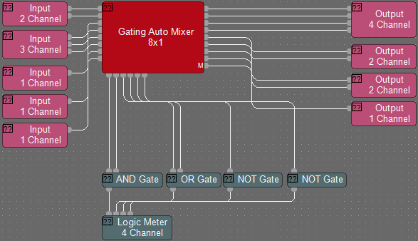
Audio signals in Tesira propagate from left to right, and logic signals propagate from top to bottom. For additional information see the Signal Lines article on Cornerstone.
Objects
Component objects can be placed into the Layout from the Audio Objects Tab, Video Objects Tab, or the Processing Library Menu.
Many components will present the user with a pop-up Initialization of configuration options. Several pre-defined options may be available for the component, as well as a 'custom' selection that allows for more specific configuration of the component. Some components allow activation of additional features from this initialization. The configuration of certain components can be further edited, even after they have been placed in the Layout and the design has been compiled.
Object Selection
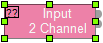
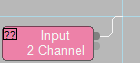
A single component object or line can be selected with a left mouse click in the layout and will show as highlighted. When more than one block object is selected one of the units will be assigned as the target, this block is always the origin for the lines. This target object is the unit referenced for alignment or wire drawing tasks.
- Green Highlight: Indicates the target object.
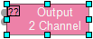
- Blue Highlights: Indicate other objects that are selected.
To select one or more objects all at once, left click on the layout behind the object(s) then drag, fully enclosing any objects in the bounding box that appears, release to select all of the objects within the bounding box. Holding Ctrl and Left Mouse Clicking objects allows the selection of one or more objects as well. There are also object selection options available from the Home Tab within the Edit section or the Surface Context Menu. Once a number of objects have been selected, the Layout tab functions may be used to organize the selected objects on the workspace.
While a single block is the target object, the label of the component object can be altered by right clicking and selecting Edit Text then typing out the label in the text box that appears.
Ports
Ports (sometimes called nodes) on component blocks are represented on blocks as selectable nodes. Each port node inhabits a 10x10 pixel space. Ports “light up” when selected, ports which are receiving line connections will "light up" as they are connected.
The label of a port can be altered by 'Shift+Left Clicking' on the port and typing out the desired label in the text box that appears.
Select one or more ports by left clicking on the layout behind the ports then drag, fully enclosing all ports within bounding box that appears, release to select all of the ports within the bounding box. If the component object the ports belong to is fully enclosed within the bounding box, that object will be selected instead of the ports.
Port Spacing
The spacing and location of ports on a block can be adjusted by using either the Port Properties Menu or the Port Spacing feature.
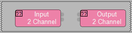
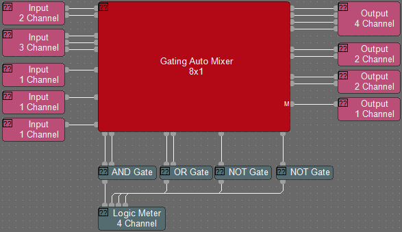
Double Nodes and Arrows
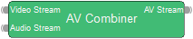
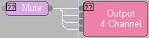
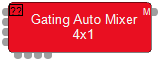
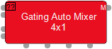
Double nodes, as seen on a AV Combiner DSP block for example, represent multi-channel audio/multi-format points.

Arrows, as seen on a partition transmitter, will show a Show all Receivers in System View option when right-clicked. Selecting this option will highlight the associated split-pass through objects in the System View window. For partition receivers, the right click menu will show a Go to transmitter option. Selecting this will jump to the partition hosting the transmitter and highlight the associated block. Double clicking the arrow port will bring up the transmitter/receiver ports dialog where links to transmitters and receivers on other partitions can be associated.
Lines
- Green Highlight: Indicates the target object.
- Blue Highlights: Indicate other objects that are selected.
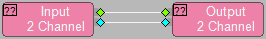
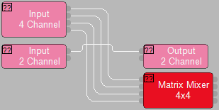
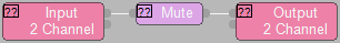
Lines represent the flow of audio signals or logic signals through the layout. They propagate from system input to system output, or from logic sources to logic receivers. Inputs can receive only one line a piece. Lines can fan out (aka "Y" or "wye") from a single output to multiple inputs on one or more blocks. To connect the ports of 2 component blocks, click on one or more ports of the first block and drag to the ports of the second, then release.
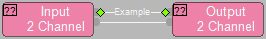
While a single line is the target object, the label of the line can be altered by right clicking and selecting Edit Text then typing out the label in the text box that appears. Line Labels can be applied to the connected ports. See Apply Line Label To Ports of the Tools Tab for additional information.
Select one or more line by left clicking on the layout behind the lines then drag and release to select all of the ports within the bounding box. Holding Ctrl and Left Mouse Clicking lines allows the selection of one or more objects as well.
Note: Line objects do not need to be fully enclosed in the bounding box to be selected.
Crosshairs
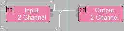
When connecting components, crosshairs make it easy to align lines with ports. "Display crosshairs" is enabled in the Display section of the Application Settings menu, see the Options page of the File Tab for additional details.
Magnification
To zoom in or out while drawing a line use the + and - keys or scrolling the mouse wheel. When not drawing a line you can zoom by holding the Ctrl key and scrolling the mouse wheel or using the zoom section options available from the View Tab.
Bends
While drawing a line, left clicking will place a flex point on the line. This allows the line path to be manually determined. If the path isn't manually selected, Tesira will automatically place any bends between one component block port to another.
Flex Points
Adding a flex point to an existing line created in Orthogonal line mode may automatically create a "line jumping" bump-out bend in the line.
- A bump-out is created with a single click on the line while holding the Alt key.
- To remove a bump-out, grab and drag the bump-out to realign it with the line. The line will "heal" itself.
- On a non-Orthogonal lines, the old behavior of adding a single flex point on the line is retained.
- Click and drag line segments to position and size the bump-out as desired.
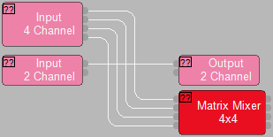
Fan Out
To connect one output to multiple inputs on a single block, click and hold the Shift key while drawing the line. As you approach a block with multiple inputs the line will fan out and automatically connect to all of the available ports.
To move the fan out lines as a group, hold the Shift key while you click on the lines and drag them to the desired location, place the cursor over a point which has all of the line segments of interest for the move.
Connection not Allowed Feedback
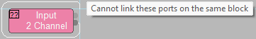
When a connection attempt is made between processing object nodes that are not compatible or that would cause a feedback loop, a red  and a textbox detailing the reason the connection cannot be made is shown.
Advance Object and Connection Management
Parallel Bends and Folded Bends
Tesira software defaults to drawing lines in parallel on the horizontal and stacked on the vertical axes. To draw lines with parallel paths, use the right and left arrow keys while drawing lines. Use the "Collapsed Line Spacing" in the Application Settings of Options to determine the spacing between the lines when the arrow keys are used. This works for both audio and logic lines. The left and right arrow keys controls the direction of spread.
Connect Audio Lines
In addition to the ability to select multiple ports and pull lines manually to the next block or group of blocks, the option to select two or more component blocks and use the right-click "Connect Audio" button is available. The keyboard shortcut is Ctrl+RightArrow.
Note: "Connect Logic" will give similar behavior, specific to logic ports on devices. The keyboard shortcut is Ctrl+UpArrow.
Lines can originate from either direction. Select the blocks to be connected. Note that the block with green handles is always the origin for the lines. Holding the Alt key while clicking on other selected blocks will select a new target object. Right-click and select "Connect Audio" (or "Connect Logic") to connect the ports.
Attach Objects Inline
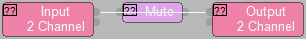
Insert a component on an existing line by placing the new component’s ports on the line and selecting the right-click option “Attach Inline” or the keyboard shortcut Ctrl+i. The ports of the component must overlap the line for the Attach Inline feature to work. It is possible to select any number of blocks before attaching.
This feature applies to both audio and logic components. Audio lines can only connect to audio ports, and logic lines to logic ports. Attaching Inline can be done using a single block or multiple blocks.
Adjusting Port Spacing
Adjusting port spacing can be used to further organize the workspace by keeping lines more direct between blocks. The spacing and location of ports on a block can be adjusted by using either the Port Properties Menu selection available from the Object Context Menu (See Menu Navigation), Port Spacing feature available under the Ports section of the Layout Tab, or the Auto Port Alignment feature described below.
Auto Port Alignment
This feature is a right-click Context Menu option that automatically repositions ports on a block to create the most direct wiring path possible to their connected blocks. This feature analyzes the existing wiring and adjusts port locations to minimize wire bends and crossover.
There are two way of selecting Auto Port Alignment:
- Left-click to select a port on a block. Alternatively, multiple ports may be selected using the control (Ctrl) or the Shift key while left-clicking.
- Right-click on one of the selected ports to open the Port Context Menu.
- Right-click on a block to open the Object Context Menu.
Then select Auto Port Alignment option from the open Context Menu.
Auto Port Alignment Behavior
Downward & Rightward adjustments: The parent block will automatically expand downward and to the right as needed to accommodate the new port positions. Both selected and unselected ports on the block will be automatically shifted downward or to the right to make space for the aligning ports.
Upward & Leftward constraints: The block will not shrink, or resize, or move upward or leftward.
External Blocks: Other blocks, and ports on other blocks, will not be moved, resized, or adjusted by Auto Port Alignment.
Unconnected Ports/Blocks: Auto Port Alignment is unavailable on ports or blocks without wiring.
Logic Simulation
Similar to the Persistent Signal Path Identifier, the Persistent Logic Simulation allows you to test logic behavior while offline. Right-click on a logic port to activate the simulation mode. Logic Simulation is available in:
- Normal Mode (follows subsequent port selection, use the Ctrl + Left Click shortcut to select the port)
- Locked Mode (remains on original port selection)
- Off (temporary selection)
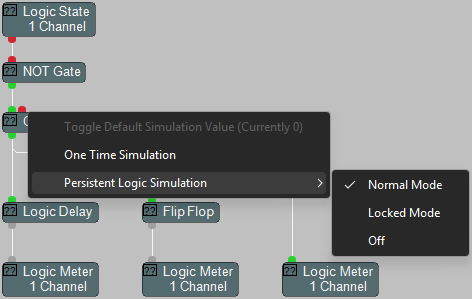
Simulation output does not trigger Presets or activate Logic Meters, rather, the logic ports “light up” in red and green to show the behavior of the logic gates in the path. Logic State controls are used as triggering events for the logic gates in simulation mode. Logic delays, flip flops and pass-throughs do not pass logic simulation.
Signal Path Identifier
See the Signal Path Identifier page of the Tools Tab for additional information.
Custom Blocks
Multiple component objects may be merged together using the Custom Block specialty component. Custom Blocks can simplify the design process by integrating frequently used component combinations, and can provide password protection for intellectual property such as unique processing and component settings. See the Custom Block section of either the Audio or Video objects pages.
Software User Interface
Once a system design is compiled and downloaded into Tesira Server devices, the system can be controlled in real-time via the Tesira software. The extent of control can be limited with different password levels.
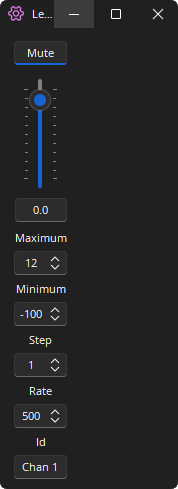
Minimizing Control Dialogs
Control Dialog Boxes for controls can be minimized, using the minimize button, to create customized Control Surfaces (room combiners, meters, level controls, mute buttons, & preset buttons). These control surfaces can then be made accessible to the User with a specific Password.
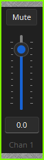
Once in the minimized state, the control surface may be moved by left-clicking and on either of the grey area along the top or bottom of the control surface. Double clicking the grey area, or using the right-click context menu, will restore the control dialog.
These control surfaces remain functional even if other component settings are made inaccessible to the User (via Password Level). The control surfaces can also remain visible even if the components they represent are made invisible (via Layer View). Therefore a custom User control surface can be created in the Layout with User access allowed but with all other system settings inaccessible (and hidden). The size and shape of the Layout may be changed and Toolbars hidden to customize the appearance of the User control screen.