System Overview
The System Tab ribbon menu provides options for options for managing media, compilation, network, and security for a system.
Media
Provides options for starting, stopping, and managing system and partition media.
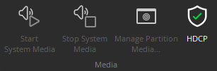
Start Audio: Enables audio signal flow within the selected system. Start Audio is available only after Send Configuration has been successfully performed.
Stop Audio: Disables audio signal flow within the selected system.
Manage Partition Media: Allows selective start/stop for each media partition in the layout.
HDCP: Use to access HDCP Managemnt (High-bandwidth Digital Content Protection) control window.
Compilation
Provides different compilation tasks to be selected and performed. Detailed information for each of these are available on the Compilation page.
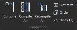
Compile: Compile the DSP layout for the active partition.
Compile All: Compile the DSP layout for all partitions.
Recompile All: Recompile the DSP layout for all partitions.
Optimize: Compile all uncompiled partitions and analyze the compilation results.
Order: Manually set the order in which partitions will be compiled.
Delay EQ: Group signal paths that are sensitive to small offsets in delay.
Network
Provides the ability to Connect, Disconnect, and Send configuration to a Tesira system. See System Considerations. for additional information about using these features. Network is also used to access system management tools, detailed below.
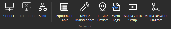
Connect: Establishes communication with, and retrieves data from, selected Tesira® systems on the network. Opens System Connect dialog box (see Connections pages). When connected to a system, Component Object Properties may be changed, but system design (objects & connections) cannot, additional details below.
Disconnect: Ends communications with selected Tesira® systems on the network. System design data is retained in software after disconnect.
Send: Transmits system design data to selected Tesira® devices in the system. Before data can be transmitted, a system design file (.TMF) must first be opened, then connected to a system, and have Tesira device IP addresses assigned (see Device Maintenance). Send Configuration will automatically Compile the system design, and reset the hardware devices, before sending the new configuration.
Network also has options for the following:
Equipment Table: Used to access the Equipment Table.
Device Maintenance: Used to access the Device Maintenance dialog.
Locate Devices: Used to access the Locate Devices dialog.
Event Logs: Used to access the Event Logs.
Media Clock Setup: Open the media network setup dialog, additional details below.
Media Network Diagram: Open the media network diagram, additional details below.
Connect
The System Connect dialog connects to a running system, sends a configuration file to a system, or open the Device Maintenance interface. From this dialog the user may connect to a running system, send a configuration file to a system or open the Device Maintenance interface.
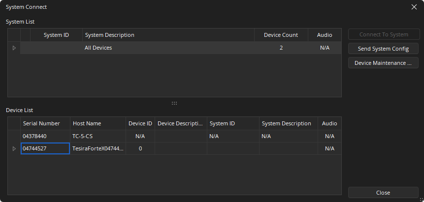
System List: To connect to a system, select the system name from the System List and click "Connect To System." The configuration file will be extracted and opened in the Tesira software. Clicking the “Send System Config” button will attempt to send the currently open configuration file to the devices identified in its Equipment Table.
- Shows all discovered, configured systems.
- Gives system ID, description, number of devices and indicates if audio is stopped or started for each system.
- Selecting All Devices displays each individual server that was discovered in the Device List, below.
Device List: When “All Devices” is selected in the System List, the Device List displays each individual server which was discovered. When a configured system is selected in the System List, the Device List displays only the discovered devices which participate in that system.
- Shows all devices based on the System List selection.
- Gives the serial number, host name, device ID (within the system), device description (if entered) or whether audio is started or stopped.
The System Connect window does not display discovered expander devices, which are only view-able via Remote Devices.
Media Networks Setup
Media Networks are the AVB, Dante or CobraNet connections that are being used in your Tesira configuration file.
Three Media networks are created by default and cannot be deleted. Additional media networks can be added and defined if required.
The available Media Networks are listed. Dedicated media blocks such as the AVB Input, AVB Output, Dante Input, Dante Output, Audio-Technica Mic, SHURE Mic, CobraNet Input and the CobraNet Output have a drop down that is used to select the required Media Network.
A single Clock Leader (Master) can be defined in the system. This setting will define which network will be tasked with Backplane timing and synchronizing the audio across different media networks. When a Dante block is added to a layout for the first time, a Media Clock Change prompt will recommend Dante Default media network to Clock Leader. See the Clocks section of Dante Considerations for additional details about clock settings. See the Media Networks section of Application settings for details on Dante Default settings.
Un-checking the Detect Clock Sync Faults suppresses the "clocks not synchronized on the media network" error message. An example of when a user may want to deselect this option is if two separate Tesira systems are connected and synchronized to the same Dante network, and each system has Dante selected as the Clock Leader. If these systems were then connected to the same CobraNet network, both systems would attempt to be the CobraNet conductor. In this scenario, only one system may be the conductor, so the other system would give the "clocks not synchronized on CobraNet network" error message. A system designer may suppress the error message by deselecting the "Detect Clock Sync Faults" check box for the CobraNet network.
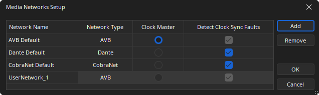
Add: Creates a default user-defined Network Name, with a format of "UserNetwork_1", "UserNetwork_2", etc. with a default type of AVB. Once created, this can be renamed and the Network Type changed to Dante or CobraNet if needed.
Remove: Will remove a selected user-defined network. Not available on any of the three default network names.
OK: Saves any current settings and closes the window.
Cancel: Discards any current changes and closes the window.
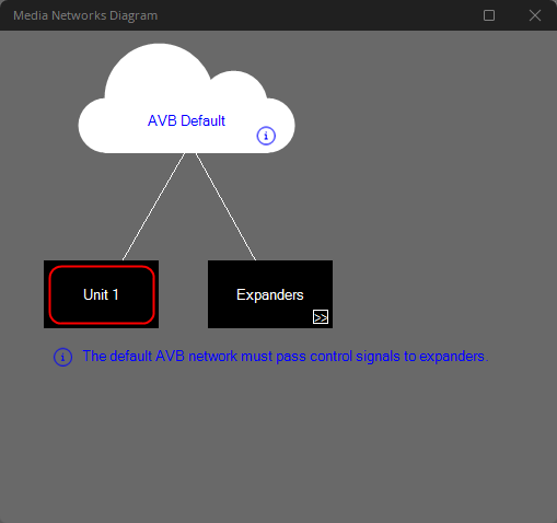
Media Networks Diagram
The Media Networks Diagram will be available after a valid Compilation has been performed. Selecting Diagram will prompt the user to perform a Compile if needed.
The dialog will show the network topology being used by all media cards in the system.
Dedicated media blocks such as the AVB Input, AVB Output, Dante Input, Dante Output, Audio-Technica Mic, SHURE Mic, CobraNet Input and the CobraNet Output have a drop down that is used to select the required Media Network.
Media Network Info and Warnings
The Media Networks Diagram has some indicators that can be reviewed for more information.
X Icon: Warning that there is an issue in the configuration or operation of the Media Network.
i Icon: User Information regarding some topology or network requirements for the Associate Media network.
Error Messages
AVB Control Required
There are expanders on the default AVB network. These expanders must be able to exchange control signals with their proxy servers. This requires exactly one of the following two network configurations. Either:
1. The default AVB network ports and control network ports must be plugged into the same network. Or:
2. If the default AVB network ports and control network ports are plugged into different networks, the default AVB interfaces on servers that proxy expanders must be enabled for control signaling via the network settings in device maintenance. This should not be done if these ports are plugged into the same network.
Disjoint Networks Present
All Tesira devices on media networks must have access to the system’s Clock Leader via one of their media network ports. This requires that there is some path from every device to the designated Clock Leader network. Such a path may pass through other devices in the Tesira system. In the current layout there are devices on media networks with no path to the Clock Leader network. These devices are indicated in red on the media networks diagram.
This error occurs when the compiler is unable to find a solution with full media-network inter-connectivity, leading to isolated media-network “islands” in the topology. To correct this problem, try to remove constraints (such as fixed allocations, etc.) that prevent the compiler from finding a connected solution. Alternately, you may add fixed-allocated blocks that force a media network connection between the isolated “islands.”
Clock Leader Unused
None of the devices in this system have media network interfaces on the designated Clock Leader network. Therefore the system cannot use this network as its Clock Leader. Either choose a different Clock Leader network in the media networks setup form, or else add blocks that utilize the designated Clock Leader.
Security
Shows the System Security and Password Options. System Security allows a system to be password protected. Protection can be applied using two methods depending if the system is Unconfigured or Configured.
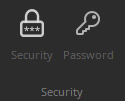
Password changes the password of the user currently logged on to the system. To change a password, select Password while logged in to the system.
Unconfigured System
If unconfigured, Device ID 0, System ID, and System Description blank as shown in Device Maintenance, this can initially be done by selecting the device and clicking Security Settings.
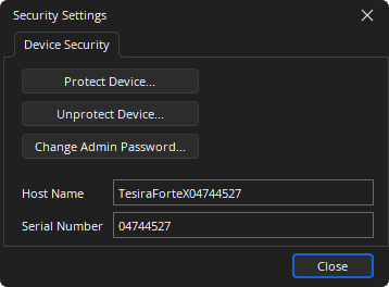
The Device Security dialog will allow the creation of an administrator password, which retains all permissions to the Tesira SERVER, SERVER I/O, TesiraFORTÉ, and Tesira Amplifier. This is applied by clicking the Protect Device button. The admin password may be changed or the system unprotected from this dialog:
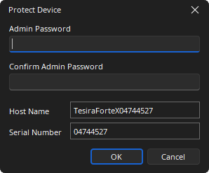
Set the Admin Password as required. Other levels of system access must be configured using the System Security dialog when connected to the system while it is configured.
Note: When two protected Tesira Servers are configured as part of the same system, the administrator passwords must match.
The Wall Plate Control Dialog allows users to create and manage security credentials for the TEC-X devices. When a user connects to the server device for the first time after opening a new Control Pad Designer session, the software will use the default credentials (the server-class device serial number). The default password may be changed through the Security Settings Wall Plate Control tab.
Change or Reset Password
Before the Wall Plate Control Change Password button can be clicked, the Protect Device must be enabled with an Admin password under the Device Security tab as previously described. Reset Password is enabled at all times.
Configured System
If configured (part of a system), protection can be applied while connected via Tesira software using the System Security Settings dialog. As in the previous case, one must first assign an administrator password that retains complete access to the system. With that accomplished, users of various types can be added to the system. Subsequent logins to the system at the administrator level will use the password with ‘admin’ as the user name.
By clicking on Add User, other users can be created with one of a few system access (privilege) levels:
Observer: Can only read system parameters in real time, i.e. meters, mixer Control Dialog, etc.
Controller: Can read and write system parameters in real time, i.e., set matrix crosspoints, set levels, etc.
Supervisor: Can do above, plus:
- Change presets
- Start or stop audio
Designer: All above, plus:
- Edit signal flow and system partitions.
Note: Only a person logged on as an administrator may:
- Create or Edit users
- Change the device’s configurable settings in Device Maintenance
- Reset/initialize the device
- Update the device’s firmware
- Add the device to a system or remove the device from a system
- Unprotect a protected unconfigured device
- Unprotect a protected system
- Change a remote device’s configurable settings via the Tesira server which is acting as a proxy when the remote device is part of the same system
- Reboot the device through TTP
- Change Password