 Equipment Table
The Equipment Table correlates specific Tesira® hardware components to the system design. Compiling a system layout will populate the Equipment Table with the most efficient hardware solution for that system. The specific pieces of hardware (by serial number or hostname) can then be chosen for each component part. This must be done before a configuration can be sent to any Tesira device(s). The option to export a copy of the devices and their details contained in the Equipment Table is available via the File menu.
Equipment Table Modes
The Equipment table will display different options depending on the software mode being used.
TesiraFORTÉ mode: TesiraFORTÉ devices are added to the equipment table automatically when TesiraFORTÉ IO channels are specified in the layout. This is done by adding TesiraFORTÉ IO channels via the TesiraFORTÉ IO Component objects. Expander devices can be specified and the following devices are available - EX-MOD, EX-AEC, EX-IN, EX-OUT, EX-IO, Lab.Gruppen Amplifier Tesira Amplifiers, Tesira Video (IDH-1 & OH-1), NPX* and EX-LOGIC devices.
Tesira SERVER mode and Both TesiraFORTÉ and SERVER Mode: Allows addition of SERVER and SERVER I/O devices. I/O Channels placed in the layout have an equipment filter to instruct the compiler to use certain hardware. TesiraFORTÉ devices are added to the equipment table automatically when TesiraFORTÉ IO channels are specified in the layout. This is done by adding TesiraFORTÉ IO channels via the TesiraFORTÉ IO Component objects. Expander devices can be specified.
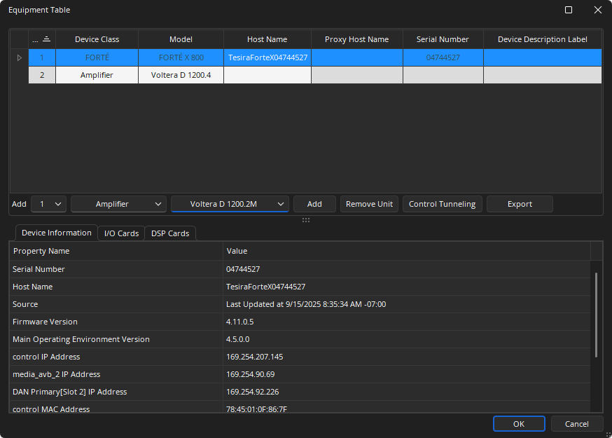
Add: Allows a SERVER, SERVER I/O, Remote expander, Rack Mount Expander, Lab.Gruppen Amplifier, Tesira Amplifiers, Logic Box, Tesira Video, TesiraFORTÉ, and TC-5D device to be specified. Multiple devices can be added at once.
Remove Unit: Will remove the selected device.
Control Tunneling: Shows serial port settings for server-class devices in the Device Information tab. See the Control Tunneling section below for detailed information.
* When multiple servers are available to proxy an NPX device, the NPX must be assigned to the unit that holds the Paging and Zone Control Block. Failing to do so will cause the device to report that there are no page codes available.
Export: Select to open the file explorer and export the Equipment List as a .CSV file. See the Export Equipment Table section of the File Menu page for additional information.
Assigning Host Names to Units
Once a design file is programmed and compiled with valid I/O blocks present these will be assigned a unit number. When physical hardware is available, the unit number can be mapped to a physical piece of hardware by using the Host name drop down to discover devices and select them into the Equipment Table.
Click on the Host Name field in the line for a given device. Select the appropriate hostname from the available units online of that type.
Note: In order for a unit to be available for assignment, it must not be part of another system, i.e., Device ID and System ID must be 0 as seen in the Device Maintenance dialog. This can be achieved by Resetting the unit from within Device Maintenance. Resetting the device clears any configuration files stored on it.
The Host Name field selects the TesiraFORTÉ, SERVER, SERVER I/O that will become the ‘proxy’ for a given remote expander or rackmount expander unit. The chosen server is then responsible for firmware and configuration updates as well of real time control of the expander. To choose the proxy host name, click in the field on the entry for any expander unit after devices have been added to the system.
To manually add a unit, select the number of devices (of the same type) to be added by using the drop down field next to the Add: text. Use the next drop down to select the device class and finally the next dropdown to select the device type. Click the Add button. This will add as many devices as requested to the equipment list. After this the Host Name and Proxy Host Name (if expander unit) can be chosen for each device. To manually remove a unit, highlight the unit in the list and click on the Remove Unit button.
Viewing Unit Configuration
When Connected to the system, the Equipment table can be viewed but not edited. The Device Information, I/O and DSP configurations of any SERVER, SERVER I/O, or TesiraFORTÉ can be viewed while connected.
Device Information
Provides details of the assigned and selected device. If no device has been assigned yet this information will be blank. Once a device has been populated in the Equipment Table the information shown on the Device Information tab will be that of the last known state. This information is available even when the configuration is viewed offline.
I/O Cards
Provides a list of the input/output cards of a selected Tesira SERVER, SERVER I/O, Lab.Gruppen amplifier, Tesira Amplifier or EX-MOD rackmount expander. Click to show the I/O configuration of a given unit. The I/O Tab will not be displayed when Remote Expanders (EX-OUT, EX-IO, EX-IN, EX-AEC), Control, (EX-LOGIC) or TesiraLUX devices are selected.
DSP Cards
Shows the internal DSP hardware (and thus DSP resources available) contained in a selected Tesira SERVER, SERVER I/O, or TesiraFORTÉ unit. The DSP Cards Tab will not be displayed when Remote Expanders (EX-OUT, EX-IO, EX-IN, EX-AEC), Rack Mount Expander (EX-MOD), Control (EX-LOGIC), or TesiraLUX devices are selected.
Control Tunneling
Control Tunneling allows bi-directional communications tunnels to be created in a Tesira system. Each Control Tunnel is point-to-point and can be configured as Serial-to-Serial or SSH-to-Serial. Once the Control Tunnels have been created, 3rd-party control products may use them to control connected devices such as displays or Pan-Tilt-Zoom (PTZ) cameras. See the Control Tunneling article on Cornerstone for additional details.
The feature is supported on TesiraFORTÉ, TesiraLUX, SERVER I/O, and SERVER devices. Control Tunneling is not supported on the EX-LOGIC.
Configuration options:
- Serial-Serial Tunnel: The Serial-to-Serial Tunnel allows two serial ports on different Tesira server-class devices (within a Tesira system) to be linked. Once configured, this tunnel behaves like a serial port extender.
- SSH-to-Serial Tunnel: The SSH-to-Serial Tunnel allows a 3rd-party controller to establish an SSH session with a Tesira server-class device (within a Tesira system) and communicate via its serial port. Once configured, the SSH Control Tunnel acts like a serial port extender using SSH. The 3rd party controller acts as a client authenticating with the Tesira device it wants to send serial commands through.
- Multiple Tunnels: Larger Tesira systems will have more serial ports available for Control Tunneling. A user may mix and match these Control Tunnel types as needed to accommodate a design.
Creating and Editing Control Tunnels
Control Tunnels are created and edited in the Equipment Table in Tesira Software. Select a server-class device from the Equipment Table and click Control Tunneling to show serial port settings in the Device Information tab.
The Control Tunneling Source may be assigned as a serial port of a Tesira server-class device in a Serial-to-Serial tunnel, or as Network (SSH) for a SSH-to-Serial tunnel. The Destination may be assigned to the Tesira serial port nearest the end device being controlled.
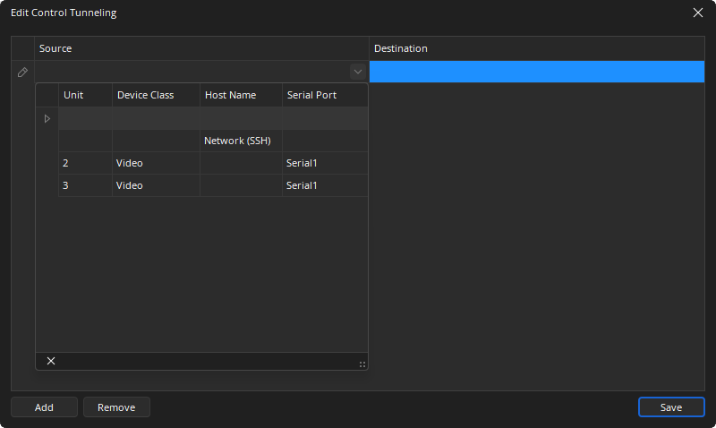
A Control Tunnel is a one-to-one assignment within the same Tesira system. If changes are made to the equipment table that affect existing control tunnels, Tesira software will give an error message.
User Authentication
Each SSH-to Serial tunnel supports one active user session at a time. The 3rd-party controller initiating the SSH session will be required to authenticate with the following credentials:
Serial port 1:
- Username: serial_control_1
- Password: (none)
Serial port 2:
- Username: serial_control_2
- Password: (none)
When the Tesira system is configured, the respective serial ports must be manually configured for Control Tunneling with the appropriate baud rate usage in as seen in the Port Settings Tab section of the Device Maintenance Network Settings page.
The baud rate configuration will be dictated by the controlled device and the 3rd-party controller and should match on each end of the control tunnel. Once set, rebooting the Tesira device(s) is recommended.
Other Considerations
If a control tunnel is active and the user causes a disruption (such as a change to a device IP address or serial port settings, reboot, etc.) the tunnel will 'break' temporarily. The system is designed to recover from this situation but could take upwards of several minutes to do so. There will be active faults associated with control tunneling during this period which will clear if the tunnel recovers successfully.