Compilation
The Compiler is a feature of Tesira software that analyses and validates the layout, calculates I/O and DSP processing requirements and makes an initial determination of the number and type of Tesira hardware needed. It attempts to find the minimum hardware and the lowest priced solution that would still realize the design. It also attempts to minimize the number of DSP cards and network connections. Additionally, a Compile will provide indication of system design errors via a compilation report in the Output Window. Finally, a Compile will perform automatic Delay Equalization on all audio paths, according to the Delay Equalization settings found under the General Settings section of the Document Settings control dialog window, which is accessed via Options in the File menu.
Compile

Compiles the DSP layout for the active partition in the overall system without regard to other partitions. In the compilation process the blocks are analyzed, checked against the system hardware (systems specified in the equipment table) and formatted to be sent to that hardware. The analysis and any logical errors in the system blocks are displayed in the output window.
Compile All

Compiles the DSP layout for all partitions in the entire system layout. In the compilation process the blocks are analyzed, checked against the system hardware (systems specified in the equipment table) and formatted to be sent to that hardware. The analysis and any logical errors in the system blocks are displayed in the output window.
The Compile All Uncompiled Partitions button is enabled regardless of the status of Delay Equalization.
Recompile All

Recompiles the DSP layout for all partitions in the entire system layout even if there have been no changes.
Optimize

Compiles all uncompiled partitions and analyzes the compilation results to find an equivalent, lower cost equipment allocation, if one exists. By default, the compiler finds an optimum equipment list for each partition in the system individually, and the accumulated result of this may not be cost optimal across the entire configuration, particularly in systems having a large number of partitions. Optimization may add or remove hardware from the Equipment Table if the list is functionally equivalent and lower cost. Devices in the Equipment Table with serial numbers assigned (physical devices) are not subject to removal by the optimization. Likewise, devices having DSP objects with fixed allocation will not be removed. If Optimization finds an improvement, the equipment table will be updated, and the entire layout will be recompiled. If no improvement is found, the previous compilation results are kept.
Order

Tesira software compiles each partition individually. Order manually sets the order in which partitions will be compiled. By default the partitions are compiled in the order in which they were created.
Occasionally, compiling partitions in numerical order can lead to undesired results or a compilation failure. For instance, the compiler might fully allocate I/O blocks to a unit in partition one so that there is no room for more I/O blocks in that unit. If subsequent partitions have I/O blocks that are fixed in the same unit, the compilation may fail.
For this reason, Tesira software allows to change the compilation order of partitions. This allows partitions to be compiled in a desired order, and may help to resolve issues like the one described above. It can also be helpful to compile partitions which have large mixer blocks before other partitions, to prevent splitting of large mixer blocks over several DSP cards.
A compilation summary can be viewed in the Output Window.
Delay

Delay Equalization provides a way to group signal paths that are sensitive to small offsets in delay. System latencies through the system will be equalized for all paths within a defined group. See the Delay Equalization section of Document Settings for information on Delay EQ modes.
Most audio and video input and output blocks are assigned to a Delay Equalization Group. Each I/O block’s Delay Equalization Group can be found in its Properties.
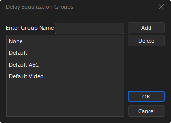
Add: User defined Delay Equalization Groups may also be created by entering a group name and selecting Add.
Delete: User defined Groups may be deleted.
The following default groups are always available:
- None: If required any block can be unassigned from a default or user-defined group. (meaning it will be excluded from Delay Equalization calculations.)
- Default: Each audio I/O block (excludes AEC Blocks) is initially assigned to the Default group
- Default AEC: Each audio AEC block is initially assigned to the Default AEC group
- Default Video: Each Video block is initially assigned to the Default Video group
Signals originating from input blocks that are in the same group will be synchronized up until the point they encounter a block with multiple inputs (e.g., mixers, routers, duckers, room combiners). Signals which feed output blocks that are in the same group are assumed to feed the same acoustic space, and will be synchronized from when they output a mixer/router block until they reach the output blocks.
Assigning an input block to the same group as an output block is allowed, but internally they will be treated as different groups. Input signals are only synchronized with other input signals, and output signals are only synchronized with other output signals.