Mics - Parle Microphones
Microphone configurations for the Parlé TCM-1, TCM-1A, TCM-X, TCM-XA and TTM-X are available. See the Parlé TCM-1, TCM-X, or TTM-X Beamtracking Mircophone Installation and Operation Guide on Biamp Downloads and the Parlé microphones section on Cornerstone for additional information.
Initialization Dialog
When the Parlé Microphone is selected the Parlé Mic Initialization Dialog window is displayed.
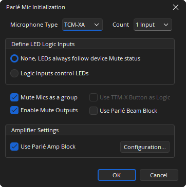
Microphone Type: Drop-down for selecting the model of microphone.
Count: Select the number of microphones supported. The maximum number available depend upon the device model.
Define LED Logic Inputs: Allows LED behavior to be customized.
- None, LEDs always follow the device Mute status: This mode hides the LED Logic Input ports and the pendant LEDs follow the default behavior.
- Logic Inputs control LEDs: Muting individual microphones in this mode has no effect on the LEDs. The state of the Logic Input ports determine the status of the LEDs.
Mute Mics as a group: Specifies whether all microphones will be muted at the same time when the mute state of a single microphone is changed.
Enable Logic Outputs: Specifies if the Logic Output ports for mute state signalling are available on the Parlé Mic block.
Use TTM-X Button as Logic: Touch buttons will act as logic input (enabled for TTM-X devices only). Option will stop the button from changing the mute state of the microphone.
Use Parlé Beam Block: Specifies if the individual beam outputs are available for use in the layout.
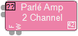
Amplifier Setting: Specifies if Parlé Amp block is to be created.
- Use Parlé Amp Block: Select to add Parlé Amp block.
- Configuration: Opens Parlé TCM-1A/TCM-XA Amp Initialization Dialog. Allows the selection of amplifier channel count.
Note: If more than one microphone input is selected for the TCM-1 and TCM-1A, the TCM-1EX expansion microphone must be used for microphones 2 and 3. If more than one microphone input is selected for the TCM-X or TCM-XA, the TCM-XEX expansion microphone must be used for microphone 2. If more than one microphone input is selected for the TTM-X, the TTM-XEX expansion microphone must be used for microphone 2. See Parlé Microphone/Amplifier Wiring Diagrams for more information on TCM-1, TCM-1A, TCM-X, TCM-XA and TTM-X topology.
Parlé TCM-1A/TCM-XA Amp Initialization Dialog.
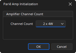
Note: The amplifier channel count and power may be selected in the software. Parlé Amplifiers have a maximum burst power of 40W per channel. They can be configured as a single channel supplying 8W RMS, or two channels supplying 4W RMS each.
DSP Block Representation
Mic Blocks for Parlé TCM-1, TCM-1A, TCM-X, TCM-XA and TTM-X provide identical basic appearance:
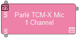
Optional:
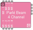
- Parlé Beam Block (TCM-X, TCM-XA, and TTM-X only)
- Parlé Amp Block (TCM-1A and TCM-XA only)
See the Logic Charts page of System Control for more information.
Control Dialog
See Parlé Software Terms and Definitions for more information.
Parlé TCM-1/TCM-1A Control Dialog with 1 Channel.
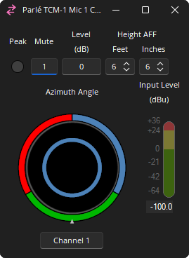
Note: Microphone Control Dialog for the TCM-1 and TCM-1A is identical.
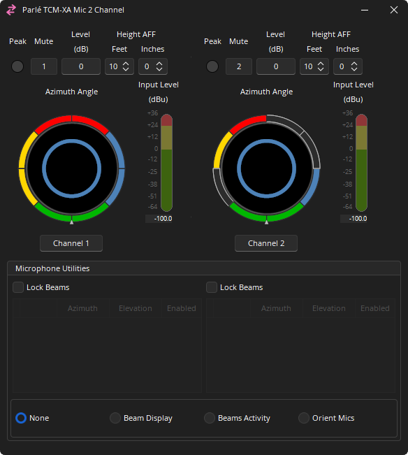
Parlé TCM-X/TCM-XA Control Dialog with 1 Channel.
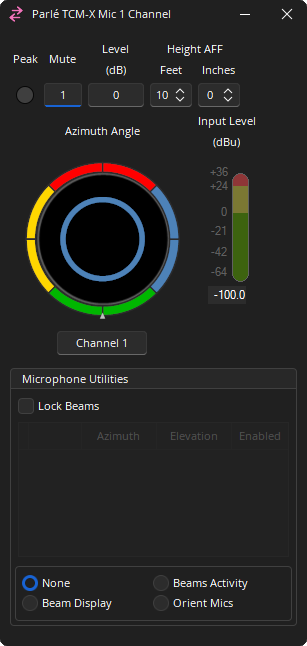
Note: Microphone Control Dialog for the TCM-X and TCM-XA is identical.
Parlé TTM-X Control Dialog with 1 Channel.
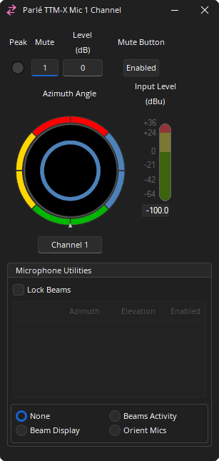
Peak: Indicates a peak condition on the microphone channel.
Mute: Mutes a single channel or all channels depending on the Initialization Dialog selection.
Mute Button: Disables the mute button located on the microphone (TTM-X only).
Level (dB): Sets the decibel level for each channel. Range of -100 to 0 dB.
Height AFF: Distance between the microphone and the floor.
- TCM-1/TCM-1A = 4'-18' (Default of 6' 6")
- TCM-X/TCM-XA = 7'-18' (Default of 10')
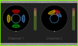
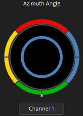
Azimuth Angle: Displays the general location of where the microphone beam is directed. Each color represents a different zone. Additional information is detailed in the Microphone Utilities section.
- TCM-1/TCM-1A = 120° lobe per beam
- TCM-X/TCM-XA/TTM-X = 90° lobe per beam
Channel Name: Text field for naming the selected channel.
Input Level (dBu): Indicates the input level of each channel. Range of -100 to 36 dB.
Microphone Utilities
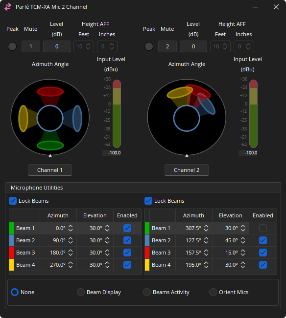
Operation Mode (default): Each beam can be enabled or disabled in 45-degree increments by clicking on the corresponding color-coded arc segment around the edge of the azimuth indicator. This allows for coverage only where it is needed. 2 channel TCM-XA Control Dialog with segments selected and unselected on channel 2. (TCM-X, TCM-XA and TTM-X only)
Lock Beams Mode: Check the Lock Beams checkbox to enable Lock Beams mode for the channel.
Customize Light Ring Behavior
Overrides LED logic behavior to allow representation of features on the physical microphone. This feature is only available when connected to an active Tesira system.
None: LED ring follows Mute status or the state of the LED logic input node.
Beams Display: Individual LEDs in the ring will be turned on or off to represent the state of the beam segments. Beams are illuminated either red or green.
Beam Activity: Individual LEDs in the ring will illuminate to show the current position of each beam as it is activated. Beams are illuminated either red or green.
Orient Mics: Select to have the physical mics illuminate with green on the front, 0°, and red on the rear, 180°, which is useful for orienting mics during installation.
Note: While a Custom Light Ring Behavior mode is selected, the device LEDs will always follow the device Mute state. This indication overrides the "Logic Inputs control LEDs" setting that may have been enabled for the block.
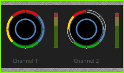
Control Surface
The minimized state of the Parlé Mic Control Dialog the Reflects the Microphone Utilities Mode selected and tracking specifications. See the Software User Interface section of the Screen Elements, Lines, and Labeling page for additional information.
Parlé Beam Control Dialog
The Beam Control Dialog is configured to show channel, mute indicators and beam controls for each segment. (TCM-X, TCM-XA and TTM-X only)
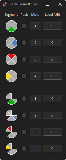
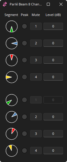
Segment: Reflects the Microphone Utilities Mode selected and tracking limits specified in the associated Parlé Microphone Control Dialog.
Peak: Indicates a peak condition on the microphone channel.
Mute: Turns the channel output signal on/off.
Level (dB): Adjusts the relative output volume. Range of -100 - 0.
Parlé Amplifier Control Dialog
The amplifier dialog is configured to show channel and device indicators and controls for each enabled audio channel.
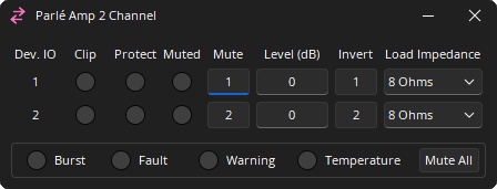
Channel Indicators and Controls
Dev. IO: Indicates which amplified output(s) are controlled with this channel of the block. Range of 1 - 2.
Clip:
- Off (grey): No clipping of the audio signal
- Red: Clipped audio
Protect:
- Off (grey): No clipping of the audio signal
- Yellow: Channel unmuted; chassis mute active
- Red: Clipped audio
Muted: Indicates the current state of the amplifier channel.
- Off (grey): Channel unmuted
- Yellow: Channel unmuted; chassis mute active
- Red: Channel mute active
Mute: Turns the channel output signal on/off.
Level: Adjusts the relative output volume. Range of -100 to 0 dB.
Invert: Adjusts the polarity of the output signal.
Load Impedance: Sets the load impedance being driven by the speaker output. 4 or 8 Ohms.
Device Indicators and Controls
Burst: Indicates a burst condition is present.
- Off (grey)
- Green: Light
- Yellow: Medium
- Red: Heavy / Warning
Fault: Indicates when a frame fault is active.
- Off (grey): No active fault
- Red: Active fault
Warning: Indicates when a frame warning is active.
- Off (grey): No active warning
- Yellow: Active warning
Temperature: Indicates a frame level thermal fault.
- Off (grey): No fault
- Yellow: Thermal warning
- Red: Thermal fault
Mute All: Mutes all channel on the Chassis.
Note: If both the Fault and Temperature indicators are red, the amplifier will shutdown until power cycle. This could be an indication of a major error in the installation.
Parlé Processing Block
The Parlé Processing block allows for easier configuration of a system to work with Parlé microphones. See Parlé Processing Audio Object under the Control section for more information on accessing processing blocks for configuring a system with Parlé microphones.
Parlé Microphone Best Practices
When configuring a system that utilizes Parlé microphones, certain practices should be taken to maximize system performance. The Parlé Processing Block offers optimal Beamtracking settings with minimal configuration. Additionally, this topic covers best practices when designing systems containing Parlé microphones outside the provided Parlé Processing Block. See the article Parlé-series Beamtracking Microphones on Cornerstone for additional information.
The Tesira Processing Library has pre-installed custom blocks. These custom blocks are recommended instead of the Parlé Processing block when AI Noise Reduction is used. Details are available in the Cornerstone article Noise Reduction and Dereverberation.
Parlé Software Terms and Definitions
Beamforming microphones are arrays of microphone elements with "beams" (polar patterns) that can be controlled and shaped via DSP, allowing the beams to be "aimed" at specific areas of the room.
Beam: A polar pattern that refers to the sensitivity of any given microphone to the sounds coming to its central axis from different angles. The location of the beam within a segment can move between the segment limits. The center of a beam will never pass its boundary start/end.
- The width of the graphic representation is the not the same as the actual beam’s width. The center of the beam represents the current location of the beam’s tracker. The edges may appear to overlap the boundary start or end, but the center should not.
Segment: The space between the boundary start and the boundary end, the segment is the "wedge" that a beam moves within when beam tracking.
Beam Tracking: The movement of a beam within a defined segment to follow the talker.
Arc: A subsection of a segment. A segment is comprised of one or more arcs that can be used to expand/contract the tracking zone that a beam can move within.
Reference Point: Aligns to the Biamp logo on the physical device.
Boundary Start: The left boundary of a segment that a beam moves within. The center of a beam will never pass its boundary start/end.
Boundary End: The right boundary of a segment that a beam moves within. The center of a beam will never pass its boundary start/end.
Layout with Processing Blocks
The image below shows settings and a layout example with four microphone inputs, the Parlé Processing Block, and the AEC Ref Block. Parlé Processing Blocks feature 1-12 microphone inputs. Logic Outputs are available for indication of the active microphones as well as if AGC is active. To place the AEC Ref Block, select "Include AEC" as shown in the Initialization Dialog.
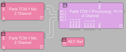
See Parlé Processing for additional information.
Layout without Parlé Processing Block
Using the Parlé Processing Block is highly recommended, however in some situations the Parlé Processing Block may not be practical. For optimal performance, the following settings should be used.
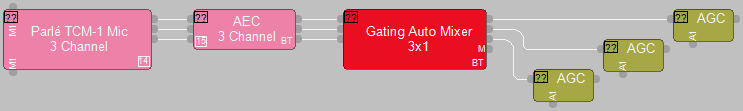
DSP Block and Settings: First, place the Parlé Mic block on to the layout with the desired number of inputs.
AEC Settings: An AEC Input Block should be placed as the next item in the signal path. Select "Preconfigure for Beamtracking Mics" (the Parlé Processing Block preconfigures AEC for Beamtracking) to ensure AEC is configured for Beamtracking. The AEC block will have a "BT" in the lower right corner when it has beamtracking enabled.
Use of the Gating Auto Mixer: Place a Gating Auto Mixer Block as the next processing object in the signal path. Select "Parlé Beamtracking" from the Preconfigure Gating Mode drop-down menu to optimize the tracking performance. The Mixer block will have a "BT" in the lower right corner when it has beamtracking enabled.
- Optionally, the check box to Enable Direct Outputs can be selected for logic tracking of the active microphone. Refer to the Logic Charts section for more information.
Placement of AGC: AGC blocks should be placed after the Gating Auto Mixer when using Parlé microphones. Placing these blocks ahead of the Gating Auto Mixer may result in unwanted sound ramping and biasing of the microphones.
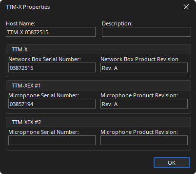
Parlé Mics Device Maintenance Properties
The Parlé Properties dialog displays the current settings of the selected Parlé device(s). This is accessed via the Remote Device Maintenance dialog menu.