 Controls - TEC-1
Tesira Ethernet Controller 1 (TEC-1) is an external remote control panel that integrates with Tesira systems via the control network, using a single CAT5 cable for control and Power-over-Ethernet (PoE). See the Tesira Ethernet Controller (TEC-1) Operation Manual on Biamp Downloads and the TEC-1 wall control configuration and overview article on Cornerstone for additional information.
TEC-1 allows for the selection of up to 32 Control Items. A Control Item can be the initiation of a logic event (such as a preset recall or a source selection), selection of a volume assignment, or both. Volume assignments may be individual or ganged levels within the layout, including Level Control blocks, as well as levels within other component blocks (such as Input/Output blocks, Mixers, Equalizers, etc) and not restricted to DSP objects on the particular partition.
Initialization Dialog
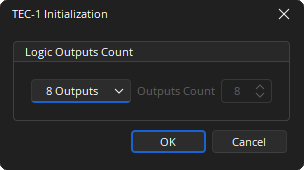
Logic Outputs Count: Logic outputs count specifies the number of logic connection points on the TEC-1 block. These connection points are typically wired to Remote Preset or Source Selector blocks but can also be used as general-purpose logic outputs. The use of Logic Gates, Flip Flops and Logic Delays allows for different priorities and functions to be assigned. If Custom is selected from the drop-down list the number of outputs between 0 and 32 can be specified.
DSP Block Representation
TEC-1 is represented in the layout as a block with a number of logic connection points (determined by the Logic Output Count setting when the block is created).

Control Dialog
Each Control Item may have a Level Control assignment, a Logic Control assignment, or both.
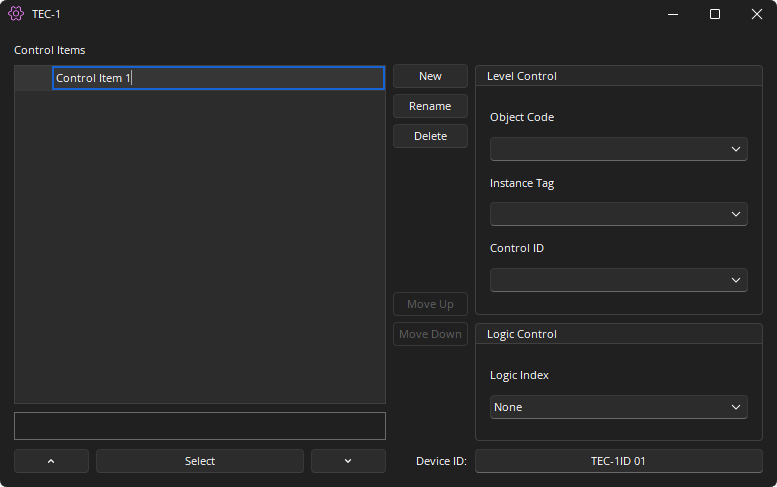
New: Creates a new Control Item in the list.
Rename: Allows a name change of the selected Control Item.
Delete: Removes the selected Control Item from the list.
Move Up / Move Down: Modifies the order of the Control Items in the list, which also re-orders the list of Control Items shown on the TEC-1 unit.
Object Code / Instance ID: Specifies the DSP object to be controlled. The text box will expand when selected and will give a list of available blocks found in the layout. If the Object Code is selected the Instance Tag is automatically entered. If the Instance Tag is selected the Object Code is automatically entered. The Object Code is assigned by the Tesira Compiler at compilation and is not user adjustable. The Instance Tag is User adjustable and must be unique.
Control ID: Selects from a list of available levels within the chosen block.
Logic Control: Logic Index specifies which logic connection point, if any, on the TEC-1 block will be triggered by a logic pulse when that control item is selected.
Select Up Arrow / Down Arrow: Once the TEC-1 block has been programmed with Control Items, the Select and Up/Down Arrow buttons at the bottom of the control dialog box may be used to mimic how the control will function from the physical panel. For example, if a volume control is selected it will display the mode in the text field above the Select Button and the Up/Down Arrow will also control the level.
Device ID: The device identifier associated to the TEC-1. This can be edited via the Properties. Note that two TEC-1 blocks in any layout must use unique Device ID's; however, multiple TEC-1 units may use the same Device ID. In that case, the units’ functions are identical and governed by the TEC-1 block with the corresponding Device ID.
Control Surface
Control Dialog Boxes for TEC-1 components can be minimized to create user control surfaces. See the Software User Interface section of the Screen Elements, Lines, and Labeling page for additional information.
Logic Output & Feedback
Certain blocks support logic feedback to the TEC-1 in order for the triangle indicator to be used to display the active function. In order for the blocks to indicate feedback they must be directly connected to the TEC-1 logic node.
The following blocks support feedback: Source Selector, Room Combiner, Flip Flop, Preset Button.
It may be that the logic circuit being used 'fans out' to multiple blocks that provide feedback logic. In this instance, a BUFFER Gate should be used to stop logic feedback on unwanted parts of the logic circuit.

The use of a Flip-Flop gate can also be used to enable feedback logic on some circuits. The Tesira compiler ignores incomplete logic circuits, so the use of another block such as a logic meter is required.
TEC-1 Device Maintenance Properties
The TEC-1 Properties dialog displays the current settings of the selected TEC-1 device and provides options to update those setting. This is accessed via the Remote Device Maintenance dialog menu.
Device ID: This must match exactly with the device ID in the TEC-1 block for the unit to receive the proper configuration menus and control the correct parameters.
Unlock Code: If the Lock Timeout is set, this Unlock code is required to unlock the unit. This is a four-digit number.
Lock Timeout: The inactivity time after which the unit will lock (in seconds). The Unlock Code will then be required to operate the unit.
Dim Timeout: The inactivity time after which the unit will dim the display (in seconds) to save power. A sensory input will bring the display back to full brightness.
Sleep Timeout: The inactivity time after which the unit will go into sleep mode (in seconds) to save power. A sensory input will bring the unit out of sleep mode.