IO - AV Input
The AV Input block serves as an interface to accept a video and audio stream input. The block represents inputs from a TesiraLUX IDH-1 to AV network streams.
Initialization Dialog
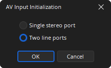
Single Stereo Port: Provides for a stereo mix of the audio received on the two physical audio inputs on the IDH-1.
Two Line Ports: Discrete ports labeled “L1” and “L2” corresponding to the two physical audio inputs on the IDH-1.
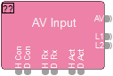
DSP Block Representation
HDCP may be enabled from the AV Input Control Dialog:
AV input with HDCP enabled: (See HDCP Management for more information)
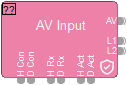
AV: The video content from the HDMI or DisplayPort.
L1 & L2: The audio content received via the two auxiliary jacks on the IDH-1.
Logic
Logic for an AV Input are as follows:
- H Con: HDMI connected
- D Con: DisplayPort connected
- H Rx: HDMI receiving frames
- D Rx: DisplayPort receiving frames
- H Act: HDMI is active
- D Act: DisplayPort is active
See the Logic Charts page of System Control for more information.
Control Dialog
Input
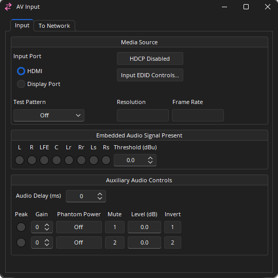
Media Source
Input Port: Allows selection between the HDMI or DisplayPort input.
Test Pattern: Changing this value from ‘Off’ will replace the video source image with the selected test pattern. Color Bar Grid HDMI 4:2:0 Test.
HDCP: Click to enable/disable HDCP function on the media source.
Input EDID Controls: Allows manual control over EDID formats.
Resolution: The currently detected resolution of the input source.
Frame Rate: The currently detected frame rate of the input source.
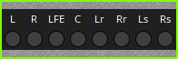
Embedded Audio Signal Present: (L) Left, (R) Right, (LFE) Low Frequency Effects, (C) Center, (Lr) Left Rear, (Rr) Right Rear, (Ls) Left Surround, (Rs) Right Surround, the Threshold setting specifies the level that the embedded audio signal will show signal present. Range of -64 - +24 dBu.
Auxiliary Audio Controls
Audio Delay: The amount of additional audio delay. Range of 0 - 64 ms.
Peak: A software indicator that flashes when the input signal is within 3dB of clipping.
Gain: Sets the amount of analog gain for that channel and is used to compensate for differing input levels (mic or line). 0- 66 dB in +6 dB steps.
Phantom Power: Assigns +48 Volt phantom power to the input for use with condenser microphones.
Mute: Turns the input signal on/off.
Level: Adjusts the relative input volume. Range of -100 to +12 dB.
Invert: Reverses the polarity of the input signal.
Note: The minimized state of the AV Input dialog will show the 8 Embedded Audio Signal Present LEDs and their labels.
High-bandwidth Digital Content Protection (HDCP)
HDCP is a form of digital copy protection that prevents copying of digital audio/video content as it travels through connections. Management of HDCP can be accessed from numerous locations. See HDCP Management for more information.
EDID Controls
EDID Management allows the user to constrain the EDID values given to the device on either the Display Port or HDMI ports.
To Network
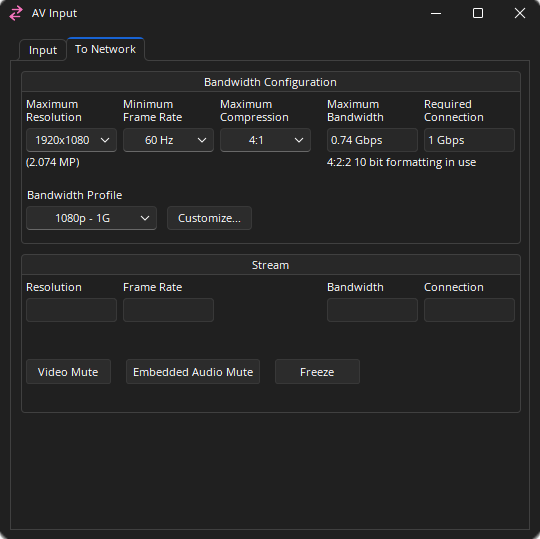
Bandwidth Configuration
Maximum Resolution: The maximum resolution allowed from the input. The number of megapixels for the resolution will be displayed below the drop-down list.
- 4096 x 2160
- 3840 x 2160
- 2560 x 1600
- 1920 x 1200
- 1920 x 1080
- 1280 x 800
- 1280 x 720
- 800 x 600
Minimum Frame Rate: The minimum frame rate allowed from the input. If a 50Hz input is used the actual frame rate may be 50, 25, or 10Hz rather than 60, 30, or 15Hz.
Maximum Compression: The maximum compression allowed from the input, Off 2:1 to 20:1.
Maximum Bandwidth: Defines the highest amount of bandwidth the expected the device will utilize. The actual bandwidth reserved will be no more than this. This value is based on the maximum resolution, minimum frame rate, and the maximum compression. Under the Maximum Bandwidth field text displaying the color sampling used is displayed.
Required Connection: Shows the bandwidth required to handle the current settings, 1 Gbps or 10 Gbps.
Bandwidth Profile: See the section below for details.
Stream
Resolution: The current resolution being streamed to the network.
Frame Rate: The current frame rate being streamed to the network.
Bandwidth: The current bandwidth being streamed to the network.
Connection: Shows which network port is currently in use.
Video Mute: When enabled a stream with all black frames is transmitted.
Embedded Audio Mute: Mutes the embedded audio.
Freeze: When enabled the current frame is held on the display.
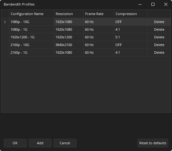
Bandwidth Profiles
Allows quick setting of the bandwidth attributes based on the expected source material type. Clicking the “customize” button will bring up an additional dialog that allows adding or modifying the list of known profiles. Changing one of the existing entries’ resolution, frame rate, or compression will modify all AV input blocks in the current layout to match the new settings. Bandwidth settings may be exported using the Export AV Bandwidth Settings option from the File menu.
Control Surface
The minimized state of the AV Input dialog will show the 8 Embedded Audio Signal Present LEDs and their labels. See the Software User Interface section of the Screen Elements, Lines, and Labeling page for additional information.