 Controls - Command String
Command String blocks allow serial control of external devices via the Serial Control Port or the IP Network. Alternatively, if active third party control feedback is required please see the Subscriptions information in the TTP section.
When a control input node along the top of the block receives a HIGH logic signal (specifically, a LOW-to-HIGH logic transition), it will trigger a user-defined string to be transmitted from the unit’s serial port or network connection. Commands can also be initiated using the Send command button within the control dialog box.
Initialization Dialog
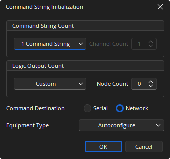
Command String Count: Provides a drop-down where the number of channels can be selected. If Custom is selected from the drop-down list the number of channels between 1 and 32 can be specified.
Logic Output Count: Provides drop-down where the number of Logic Outputs can be selected. If Custom is selected from the drop-down list the number of nodes between 0 and 32 can be specified.
Command Destination: Select either a Serial port or Network (IP) port.
Equipment Type: Specifies what type of hardware the Compiler should allocate the block to. Review the Equipment Type section for more details.
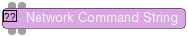
DSP Block Representation
Network Command String:
Serial Command String:

See the Logic Charts page of System Control for more information.
Control Dialog
Network Command String
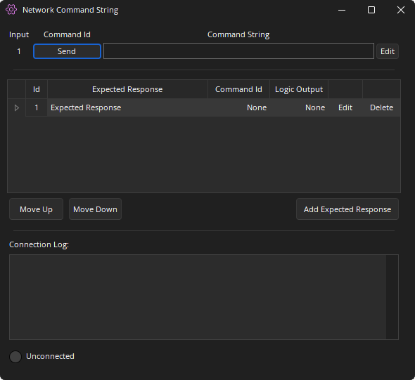
Input: Relates to the corresponding logic Input.
Command ID: The send button allows manual transmission of the command string.
Command String: Shows the data that will be sent.
ID: Number that relates to the corresponding Expected Response.
Expected Response: User defined character string to be used in pattern matching.
Logic Output: Allows a Logic Output node to be associated with an Expected Response. The Logic Output will momentarily pulse a logical HIGH ( for 250ms).
Edit: Allows editing of the respective Command String or Expected Response.
Move Up / Move Down: Allows the Expected Response string order to be re-ordered as needed. This is important because the pattern matcher starts at the top of the list and works its way down looking for a complete match.
Connection Log: Displays character strings sent/received while connected to a live system.
Status LED: Shows Connection Status and Communication Activity.
Serial Command String
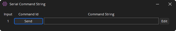
Input: Relates to the corresponding logic Input.
Command ID: The send button allows manual transmission of the command string.
Command String: Shows the data that will be sent.
Edit: Opens the Edit Command String Dialog.
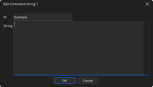
Edit Command String Button
The Edit Command String button applies to both the Serial Command String block and the Network Command String Block.
Selecting the Edit button will display the following dialog and allow the Command ID name and String to be defined.
Control Surface
Control Dialog Boxes for Command String components can be minimized to create user control surfaces. See the Software User Interface section of the Screen Elements, Lines, and Labeling page for additional information.
Properties Sheets
Network and Serial properties menus are docking menus. See the Docking Menus section of the Menu Navigation page for additional details.
Network Command String Block Properties
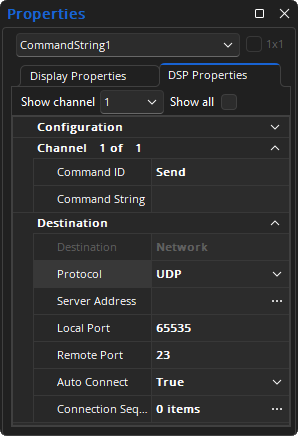
Command ID: The send button allows manual transmission of the command string.
Command String: Shows the character string that will be sent.
Destination: Identifies connection type as Network or Serial, defined at block initialization.
Protocol: Defines transport type as TCP or UDP.
Server Address: Target IP or hostname of the 3rd party network device the block will be communicating with.
Local Port: (UDP only) The local port, on Tesira, that will be used. 0 - 65,535.
Remote Port: The target port at the previously defined Server Address target IP that will be used. 0 - 65,535.
Auto Connect: Attempts to establish session communications automatically. Re-connection attempts will recur every 3 seconds as needed.
Connection Sequence: Intended for session negotiation sequence.
The Connection Sequence is a list of strings that the Tesira Server monitors for a match and will return a response as defined in this list. For example, if a command string from third party device (sent to Tesira) matches any of the Connection Sequence items, the corresponding ‘Response’ string will be sent back to the 3rd party control device.
Since the 3rd party control device can send a string of any length, with or without special characters and/or spaces and new lines, it can be difficult for an exact match to occur. Extra care should be taken when defining the values sent and what is expected to be received when configuring this list. Clicking the '...' button will display the Connection Sequence dialog where the Connection and Response values can be specified.
Serial Command String Properties
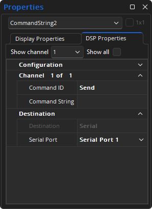
Command ID: The send button allows manual transmission of the command string.
Command String: Shows the character string that will be sent.
Destination: Identifies connection type as Network or Serial, defined at block initialization.
Serial Port: Allows selection of available serial ports on the hardware device as available.
The Serial Command String block will only transmit strings from serial port of the unit to which the block has been allocated. On a SERVER I/O and SERVER, it can be either of the ports depending on how they are configured. On TesiraFORTÉ, TesiraLUX, and the EX-LOGIC there is only one serial port. The Property Sheet allows selection of which port is used.
Consider fixing the allocation of Command String blocks to prevent the block from being unexpectedly allocated to the wrong device.
The Baud rate for the serial port for the SERVER I/O, SERVER, TesiraFORTÉ, and TesiraLUX is configured in Device Maintenance under Serial Port Settings.
The Baud rate for the serial port for the EX-LOGIC is configured in Expander device maintenance in the EX-LOGIC Serial Device Settings section.
Response Pattern Matching
ASCII: These are case sensitive and most commonly alphanumeric and human-readable characters. Example: Power_On
Escape Character: This is a character used to indicate that the following two characters will be hexadecimal digits. Example: ~0A
?: A question mark (?) is a wildcard that will match any single printable character (including space but excluding carriage return, line feed or newline) in the input.
*: An asterisk (*) in the pattern matches zero or more printable characters (including space) in the input. The asterisk matches as few characters as are necessary to find a match in the input.
The block matches against each Response Pattern to receive input from the remote device. This includes previously received, but unmatched data remaining in the input buffer.
- The block removes the matching bytes from the input when the first part of the input matches a pattern. It then sends the selected Command String (if any) and pulses the selected Logic Output (if any). Unmatched bytes remain in the receive buffer for future matches.
- The block waits indefinitely for additional input when the entire input matches the initial portion of any pattern, but not the complete pattern.
- If the input does not match any pattern, the block discards the first byte of the input and tries to match the remaining input.
Both the order and content of the patterns are important. The following guidelines are recommended:
- Start Response Patterns with a character or count of characters. Response Patterns starting with “*” or “?*” can cause the block to quit responding while it waits for additional input.
- Include trailing NL (~0A), CR (~0D) or CR-LF (~0D~0A) in Response Patterns.
- Do not include an asterisk (*) at the end of a Response Pattern. This is not allowed by the Tesira software or firmware.
Device Indicators and Controls
Response Commands: Indicates expected response.
- Yellow - Receiving response
- Green - Response received
- Red - Response command receive error
- Red - Response command receive overflow (Fault will be logged in Event Logs)