 Comms - VoIP Phone
The VoIP Phone provides support for IP phone systems. When the VoIP phone is selected from the Object Toolbar, an initialization dialog is displayed.
Initialization Dialog
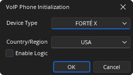
Device Type: Specifies what type of hardware the compiler should allocate the block to. Review the Equipment Type section for more details.
Contry / Region: A drop-down menu to select the country in which the system will be operating, this configures the local call progress tones accordingly.
Enable Logic: If checked, the logic support is shown on the VoIP Control/Status block.
DSP Block Representation
Default VoIP Block
The VoIP Phone is comprised of a VoIP Receive, VoIP Transmit and VoIP Control / Status blocks. The three blocks will have a number on the lower right, assigned by the software, which indicates which blocks are associated with each other, which is important when there are multiple VoIP Phones in the system. In addition, a dialer block or HD-1 can be associated with telephone or VoIP interfaces. The Dialer and HD-1 control are available in the Audio Objects tab under the Control section.

![]()

See the Logic Charts page of System Control for more information.
VoIP X Control/Status takes the user to a web user interface.

![]()

Control Dialog
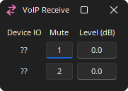
VoIP Receive and Transmit
The VoIP Receive block is an input for received audio coming into the system via the VoIP interface. The VoIP Transmit block is an output to the VoIP telephone system.
![]()
Device I/O: Indicates which physical hardware input is associated with that software channel. For Server and SERVER-IO devices is formatted as x.y - where x indicates which card slot and y indicates which channel on the card.
Mute: Turns the input signal on/off.
Level (dB): Adjusts the relative input volume. VoIP Receive range is -100 to 12 and the VoIP Transmit range is -100 to 0.
VoIP Control Status
The VoIP Control/Status features a view toggle that switches between standard and an advanced viewing mode. The standard view contains information and options relevant to most VoIP implementations. Advanced view allows selection and customization of more complex VoIP options. Some items may be modified while connected to the system while others may require being offline to be modified.
Use the Line Select buttons to display line 1 or 2 for editing or viewing. Several tabs show screens for setting general properties and viewing status information about the VoIP Phone when the system is connected.
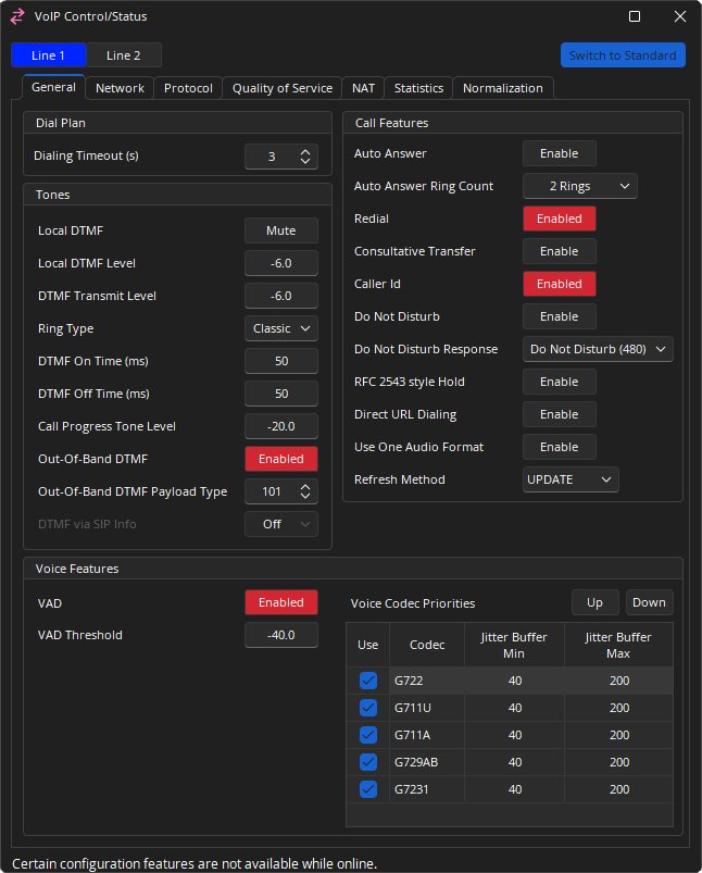
Dial Plan
Dialing Timeout(s): Specifies how long after the last digit is entered before the VoIP phone will consider the dial string complete and submit a dial request. The range is 0 - 20 seconds.
Tones
the VoIP card supports inband DTMF, out of band DTMF (using RFC2833) and DTMF via SIP Info. The three DTMF modes are mutually exclusive.
Local DTMF: Mute turns local DTMF generation on or off.
Local DTMF Level: Controls the local volume of generated DTMF tones.
DTMF Transmit Level: Controls the transmitted DTMF tone level.
Ring Type: Selects whether the standard ring tone will be heard or not (Classic or Silent) when a call comes into the VoIP Phone.
DTMF On Time (ms): Sets the duration of generated DTMF tones.
DTMF Off Time (ms): Sets the length of the pause between successive DTMF digits.
Call Progress Tone Level: Controls the volume of call progress tones, such as the dial tone, busy tone and other signals.
Out-Of-Band DTMF: When this button is enabled all DTMF signals will be sent to the far end via RTP Events in the RTP stream.
Out-Of-Band DTMF Payload Type: This selection allows you to set the RTP Payload type reserved for Out-of-Band DTMF signals. 101 is the most typical (and default) setting for Out-of Band DTMF however if this Payload Type is in use for something else it can be changed to something that is available. The range is 97 - 127.
DMTF via SIP Info: When this feature is enabled all DTMF signals will be delivered using SIP protocol. Setting the SIP Info to Normal will include the DTMF digit information as well as the duration of the DTMF tone. Setting the SIP Info field to Simple will only deliver the DTMF digit information.
- Note: If Out-of-Band DTMF is disabled and SIP Info is set to off the SVC-2 card will revert to using In-Band DTMF. This means DTMF tones will be produced by the SVC-2 card and sent to the far end as audio using the selected VoIP CODEC. This may be required if the far end device does not support one of the VoIP DTMF signal transfers mentioned above.
Call Features
Auto Answer: Pick up the call automatically after the ring count duration has passed.
Auto Answer Ring Count: May be set to immediately, 1, 2, or 3 rings.
Redial: Allows the previously dialed number to be recalled.
Consultative Transfer: The transfer process will connect the second party to a third party after the third party answers and agrees to take the call (support is dependent on phone system). See VoIP Transfer Commands for further information.
Caller ID: Shows the Caller ID in TTP updates and the Dialer.
Do Not Disturb: Can be enabled or disabled.
Do Not Disturb Response: The message sent to the proxy advising it of the do not disturb state.
RFC 2543 Style Hold: Support for RFC 2543 hold signalling.
Direct URL Dialing: Allows a specific telephone extension or number to be dialed using the URI format.
Use One Audio Format: Acknowledges the SIP "invite" with multiple audio format or one audio format.
Refresh Method: A mode of UPDATE or Re-INVITE can be specified.
Voice Features
VAD: Voice Activity Detection, when level is not detected network packets will be restricted to save bandwidth.
VAD Threshold: Sets the level the signal must fall below for VAD to be enabled. The range is -64 - 24 dBu.
Voice Codec Priorities: A list of supported voice codecs is shown in descending order of priority.
- The Up and Down buttons can be used to change the priority order of the selected codec.
- Remove the check from the Use column to remove that codec from use.
- Jitter Buffer Min and Max can be set to compensate for network conditions. Increasing the buffer sizes may improve call quality at the expense of additional delay. Decreasing the buffer sizes may improve delay at the expense of call quality. These settings are adjustable per codec, per line.
Network Tab
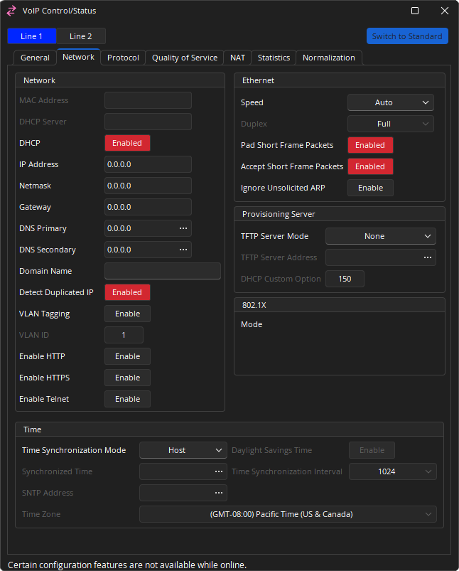
Network
MAC Address: Displays the unique hardware identifier.
DHCP Server: Is a network server that automatically provides and assigns IP addresses, default gateways and other network parameters to client devices.
DHCP IP: IP assignment from a DHCP server.
IP Address: If DHCP is enabled, the DHCP server should provide the IP Address, Subnet Mask, Gateway, and Primary/Secondary DNS. Otherwise, these settings can be added manually.
Domain Name: This setting specifies the search domain for DNS names. For example, if the domain is set to "example.com" and the proxy is set to "voip", the result would be "voip.example.com". This setting is only enabled when DHCP is not being used. Otherwise the DHCP server can provide the domain details.
Detect Duplicated IP: If DHCP is enabled on the SVC-2 and a device is added to the network with the same IP, the conflict will be reported in the Event Logs and the card restarted to request a new IP. If a static IP address is being used for the SVC-2 card, the conflict will be reported in the Event Logs as well, but the card may remain in a conflicted fault state until being manually restarted.
VLAN and VLAN ID: When enabled, the VoIP card will only respond to and transmit to packets tagged with this VLAN ID number. VLAN's can also be configured by switch port. This option should only be enabled if requested by the network administrator.
Enable HTTP: This will enable HTTP access for the VoIP interface (port 80). Once enabled, a VoIP webpage is accessible at the IP address of the SVC-2 card over the network. This will allow VoIP to be configured over the network. This setting may be disabled if network security is an issue. For more information see the VoIP Webhelp.
Enable HTTPS: This will enable HTTP access for the VoIP interface (port 443). Once enabled, a VoIP webpage is accessible at the IP address of the SVC-2 card over the network. This will allow VoIP to be configured over the network. This setting may be disabled if network security is an issue. For more information see the VoIP Webhelp.
Enable Telnet: This will enable Telnet connections to the VoIP interface (port 23). This is an engineering diagnostic interface only. For installations with security concerns about this port being open it should be disabled. There is no end user configurable settings in the engineering diagnostic interface and is password protected.
- Note: HTTP/HTTPS webpage access: a configuration with HTTP or HTTPS enabled will be accessible over the network by entering https://xxx.xxx.xxx.xxx (Tesira VoIP's IP address), https://abc (hostname), or https://abc.xyz.com (FQDN). Default login credentials are: Username: admin / Password: admin
Ethernet
Settings for speed and duplex properties of the VoIP Phone card.
Speed: Allows setting Ethernet speed to Auto, 10 Mbps or 100 Mbps.
Duplex: Allows setting to full or half duplex.
Pad Short Frame Packets: Allows padding (adding zeros) to avoid short or "runt" Ethernet dataframes.
Accept Short Frame Packets: Enables/disables accepting short or "runt" Ethernet dataframes.
Provisioning Server
TFTP Server Mode: Allows setting the TFTP server mode to one of the following.
- None
- Static
- DHCP 66
- DHCP Custom (String)
- DHCP Custom (Binary)
802.1X
Authentication Status: Gives the authentication status of 802.1X.
Mode: Gives the established protocol for authentication.
EAP-FAST Provisioning: If Mode is set to EAP-FAST, gives the status of the provisioning (Authenticated or Unauthenticated). No text is shown if Mode is set to anything other than EAP-FAST.
- Note: All data in this window is read-only and is configured from Device Maintenance. See Configure_802.1X for more information on these settings.
Time
Time Synchronization Mode: If Static is selected the Synchronized Time field should be used. If SNTP is used the time will be taken from a SNTP server. If Host is selected the VoIP card time will be synchronized to the host server devices time.
Synchronized Time: Will be available if the Time Synchronization Mode is set to Static. Shows the VoIP Phone's time as obtained from the network or as set in the DSP Properties tab in Properties of the VoIP Control/Status block. This will e used for authenticating security certificates which depend on time stamps.
SNTP: Address specify the address of the time update server providing automatic network time synchronization.
Daylight Savings Time: Will automatically update the time if configured for a region that uses daylight savings.
Time Synchronization Interval: If SNTP is used the time update interval can be set.
Time Zone: If SNTP is used the locale can be set.
Protocol Tab
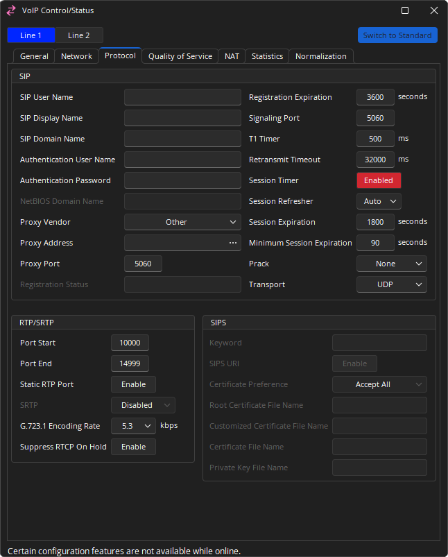
SIP
SIP User Name: Alphanumeric string that identifies the VoIP extension on the network. It is the number or string you would need to dial to reach this extension.
SIP Display Name: String used for Caller ID name purposes.
SIP Domain Name: The SIP domain name to be used.
Authentication User Name / Authentication Password: The credentials needed to register and authenticate with the VoIP proxy server.
NetBIOS Domain Name: Only editable if Proxy Vendor is set to Skype For Business.
Proxy Vendor: Choose the entry that matches the phone system the VoIP Phone is integrating with. Possible selections are Other, Avaya SES, Avaya SM, Avaya IP Office, Avaya CS1000, Cisco, Skype for Business, Mitel and ShoreTel. If an exact match does not appear in the list, select Other.
Proxy Address: Network address of the VoIP proxy server.
Proxy Port: The network port the VoIP Phone should use to communicate with the proxy server. Port 5060 is a standard port used in VoIP systems, but may be modified as required.
Outbound Proxy Address / Outbound Proxy Port: May be set if a separate proxy server is used for inbound versus outbound traffic to specify the network address and port number of the outbound server. Most IP phone systems use a single proxy server for inbound and outbound, in which case Outbound Proxy Address should be left blank.
Registration Status: Details of the state of registration.
Registration Expiration: Determines the interval the VoIP line will attempt to re-register with the Proxy. The proxy may override this setting with a value of its own. If an acknowledgement has not been received from the Proxy within the agreed time the VoIP card registration information kept in the proxy's database will be cleared. The default registration expiration period is 3600 seconds and should be left at this value unless specified by the network administrator. May be set between 60 to 86400 seconds.
Signaling Port: The signaling port is used to direct incoming SIP traffic to the correct line for communications between the VoIP card and the proxy. The default port for Line 1 is 5060 and the default port for Line 2 is 5062. These settings should be left at this value unless specified by the network administrator.
T1 Timer: This timer is used when sending requests over UDP. If the response is not received within this interval, the request is retransmitted. The retransmission interval is doubled after each retransmission.
Retransmit Timeout: The total amount of time the card will continue to retransmit a UDP packet that has not been responded to.
Session Timer: Enables periodic refresh of SIP sessions through a Re-INVITE or UPDATE request. When disabled, the Session Refresher, Session Expiration and Minimum Session Expiration options will be disregarded. If a call unexpectedly disconnects, disabling this option may help.
Session Refresher: In a SIP session that utilizes a session timer, the Session Refresher is the device that will send the periodic Session Refresh requests to refresh the session.
-
Auto: Default setting allows both ends of the call to negotiate who will be the refresher. This usually leaves the decision to the device receiving the SIP packets.
-
UAS: User Agent Server (UAS) is the VoIP device that responds to the SIP Request. For a phone call, it is considered the “called” device. This setting makes sure the SVC-2 card will only negotiate to a Session Timer where the UAS is nominated as the refresher.
-
UAC: User Agent Client (UAC) is the VoIP device that sends the SIP Request. For a phone call, it is considered the “calling” device. This setting makes sure the SVC-2 card will only negotiate to a Session Timer where the UAC is nominated as the refresher.
-
Local: This setting makes sure the SVC-2 card will always be the refresher of a Session Refresh.
-
Peer: This setting makes sure the SVC-2 card will never be the refresher of a Session Refresh.
Session Expiration: Determines the interval the VoIP card will try to negotiate with the Proxy to keep the VoIP session alive. Note that the proxy may override this setting with a value of its own. If a Session Refresh request is not properly received by both parties within this agreed time, the session will expire and the call ended. This may be set between 90 to 65535 seconds; the default value is 1800 seconds.
Minimum Session Expiration: If the proxy tries to override the Session Expiration value as specified in the VoIP card, the time entered in this field will be the minimum value allowed. This may be set between 90 to 65535 seconds; the default value is 90.
Prack: Guarantees a reliable and ordered delivery of provisional responses in SIP. PRACK Improves network reliability by adding an acknowledgement system to the provisional Responses. Can be set to None, Supported, Required.
RTP/SRTP
Port Start: The first RTP Port used by this line. Must be between 4000 - 65534 and must be one less than the Port End.
Port End: The last RTP port used by this line. Must be between 4001 - 65535 and must be one more than the Port Start.
Static RTP Port: Static Real-time Transport Protocol Port is the Port number used for RTP traffic.
SRTP: Secure Real-time Transport Protocol provides encryption of the RTP audio data. Available if Transport is set to TCP or TLS. Go To VoIP Control/ Status Block, open the property sheet DSP properties, Set Protocol SIP-Transport to TCP or TLS. Can be set to Disabled, Allowed, Preferred or Required.
G.723 Encoding Rate: Used to define the G.723 bit rate. The options available are 5.3 and 6.3 kbps.
Suppress RTCP On Hold: This parameter determines whether RTCP packets continue to be sent across the trunk for calls that have been placed on hold.
SIPS
SIPS Keyword: This field is used to enter the keyword used for secure SIP on a per-Line basis. To enable Secure SIP, set the Transport mode to TLS.
Certificate Preference: Can be set to Fully Verify, Trust, Keyword, or Accept All.
Root Certificate File Name, Customized Certificate File Name, Certificate File Name, and Private Key File Name can all be specified.
- Note: Certificates uploaded via the VoIP Management Webpage will not be shown in the SIPS data as detailed above. Tesira software must configure certificates or the private key filename and VoIP will retrieve the files from the provisioning server if the server is configured.
Quality of Service
Only available while Advanced view is selected.
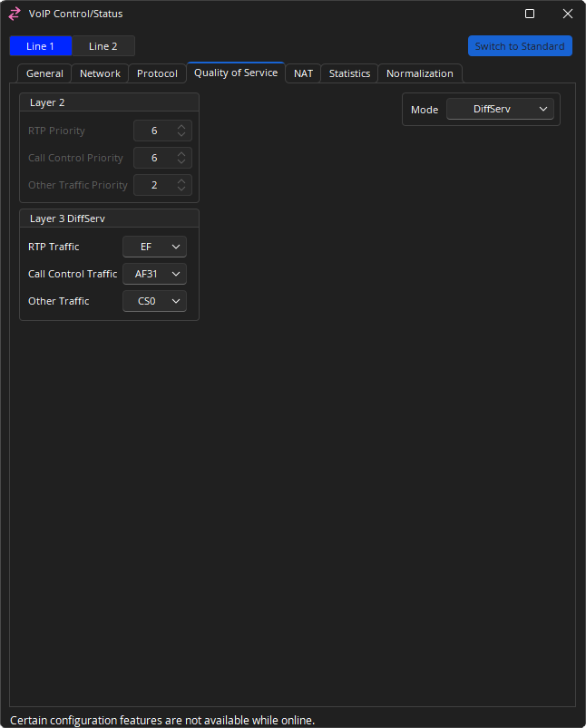
Layer 2
RTP Priority and Call Control Priority QoS levels can be set, if QoS Mode is set to TOS and VLAN is set to Enabled. Numerical priorities 0-3 are low priority; 4-7 are high priority.
Layer 3
Layer 3 DiffServ: RTP Traffic and Call Control Traffic levels can be set if QoS Mode is set to DiffServ (Differentiated Services).
Layer 3 TOS: Allows turning enabling or disabling service variables shown above, as well as level of RTP, SIP and Other Precedence. Entries with a numerical priority is set on a range of 0-7, 0 being lowest and 7 being highest. This determines the priority of traffic for the respective type of service. Type of Service settings also control the efficiency at which data packet traffic is forwarded. Enabling will determine traffic settings of RTP, SIP or Other, respectively:
- Min Delay: data packets will be forwarded with minimum delay.
- Max Reliability: data packets will be forwarded with maximum reliability.
- Max Throughput: data packets will be forwarded with maximum throughput.
- Min Cost: data packets will be forwarded with minimum cost to network bandwidth.
NAT
Only available while Advanced view is selected.
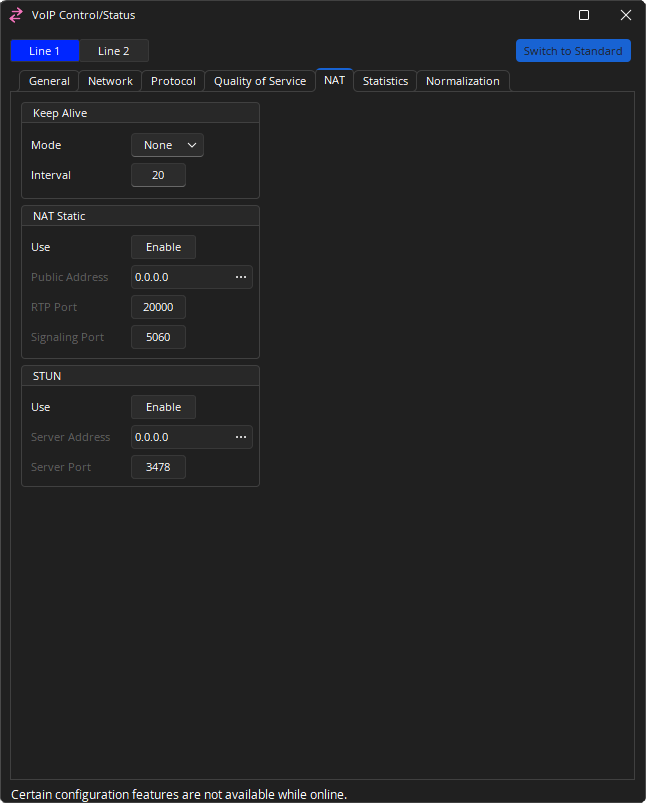
Keep Alive: Mode sends a packet at defined intervals to keep a firewall port open. Mode defines the type of packet sent, and may be set to None, Options, Register or CRLF. If set to anything other than "None," Interval may be set to 20 to 30 seconds; default is 20.
NAT Static: When NAT Static is enabled, a network admin may allow the VoIP endpoint to use a static port assignment through a firewall. A public address can be entered and an RTP Port and Signaling Port specified.
STUN: When STUN is enabled, a VoIP endpoint can use an external STUN server to keep firewall ports open. The Server Address and Server Port can be entered in the VoIP configuration. Enabling one of these options disables the other.
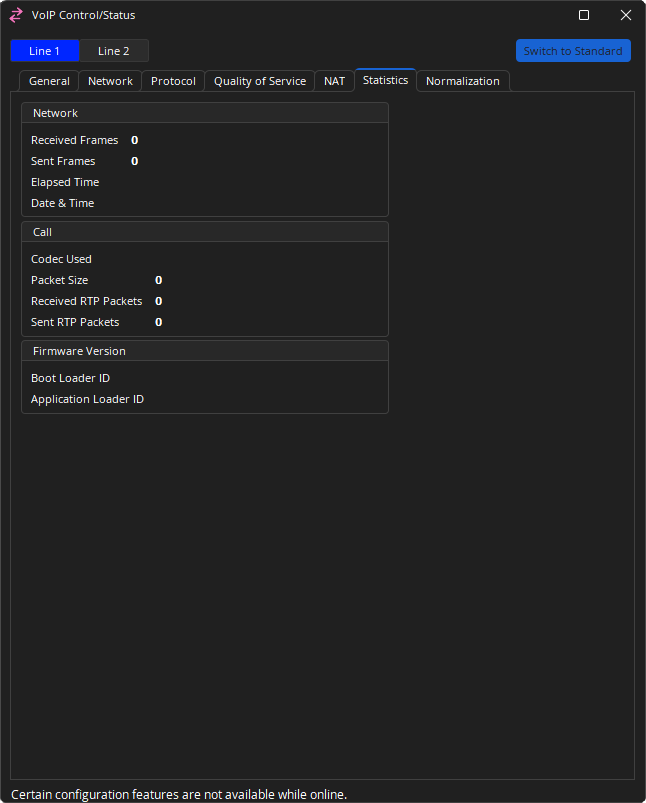
Statistics
When connected to a system, the Statistics Tab displays read only information. The settings displayed here include network, call, and firmware version information.
Normalization
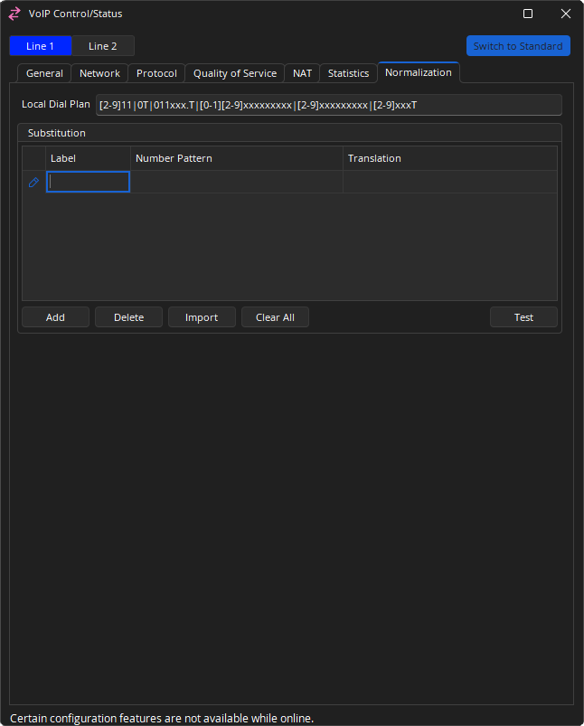
Local Dial Plan: is a regular expression which determines dialing behavior according to the method specified in RFC 3435. Use the default Local Dial Plan string unless an alternate one has been provided for you. Default Local Dial Plan: [2-9]11|0T|011xxx.T|[0-1][2-9]xxxxxxxxx|[2-9]xxxxxxxxx|[2-9]xxxT
Substitution: Microsoft Lync/Skype For Business uses .NET Framework regular expressions to specify numeric match patterns that the server uses to translate dial strings to E.164 format for the purpose of performing reverse number lookup. The substitution dialog allows the definition of similar normalization rules to allow the Tesira VoIP card to automatically translate the dialed digits to E.164 format. Multiple rules can be defined. Each rule includes a label, a matching pattern, and a translation pattern. The rules are based upon lines.
- Add: Allows the creation of a new rule
- Delete: Will remove the selected rule
- Import: Allows importing of XML files generated by the Lync Server. Selecting Import brings up an Open File Dialog which enables selection of the generated XML file.
- Clear All: will delete all rules
- Test: Allows substitution entries to be confirmed. Select the row to test this will bring up a dialog with the selected row’s number pattern and translation rule loaded. Numbers can be added and the translated output verified.
Once substitutions have been added, a right click context menu is available allowing the option to Copy all rows, Copy selected rows or a Paste to bottom function.
Note: Up to 100 rules may be created in Tesira, yet the users of the VoIP Web Management are limited to saving a maximum of 50. If 50 or more rules have been created in Tesira, a user will not be able to save new rules in the VoIP Web Management interface. The VoIP WebHelp may be accessed for further information.
Useful normalization rules
Tesira VoIP follows .Net framework regular expression to create matching rules and is a subset of .Net framework regular expression. Multiple number pattern and translation rules can be created. The number pattern and translation rule must be present as a pair. More details can be found in the article Number Normalization Rules in Lync or Skype For Business on Cornerstone.
The below gives some basic information:
- \d - Matches any decimal digit
- ^ - The match must start at the beginning of the string
- $ - The match must occur at the end of the string
- (subexpression) - subexpression
- {n} - Matches the previous element exactly n times
- $number - the substring matched by group number
The table below gives some examples and explanations about the rules.
| Use Case | Number Pattern | Translation | Example | |
|---|---|---|---|---|
| Translates 4-digit extensions | ^(\d{4})$ | +1503718$1 | 1234 is translated to +15037181234 | |
| Translates 5-digit extensions starting 5 | ^5(\d{4})$ | +1503718$1 | 51234 is translated to +15037181234 | |
| Translates 7-digit numbers | ^(\d{7})$ | +1503$1 | 7189238 is translated to +15037189238 | |
| Translates 10-digit numbers | ^(\d{10})$ | +1$1 | 5037189238 is translated to +15037189238 | |
| Translates numbers with long distance prefixes | ^1(\d{10})$ | +$1 | 15037189238 is translated to +5037189238 | |
| Translates numbers with international prefixes | ^011(\d*)$ | +$1 | 011915037189238 is translated to +915037189238 | |
| Translates 0 to an operator | ^0$ | +15037180100 | 0 is translated to +15037180100 | |
| Translates numbers with prefixes | ^5678(\d{4})$ | +1503718$1 | 56781234 is translated to +15037181234 | |
VoIP Web Management
Many of VoIP configuration settings available in Tesira software for TesiraFORTÉ, FORTÉ AI, FORTÉ CI, FORTÉ VT, FORTÉ VT4, FORTÉ TI and FORTÉ VI are available via the VoIP Management Webpage. The VoIP Management Webpage allows users to set up, configure and manage all VoIP functions of Tesira products from an intuitively-designed web interface. The VoIP Management Webpage is designed for users that only intend to configure and maintain functions of a VoIP endpoint; proficiency in Tesira software is not required.
Note: Once configured, the FORTÉ X VoIP settings are available only through the web user interface.
Information required to access and configure via the VoIP Management Webpage is available on the front panel of a Tesira device:
- IP Address
- Netmask
- Gateway
- Enabling VLAN
- VLAN ID (if VLAN is enabled)
The VoIP Management Webpage can only be accessed via VoIP network. If VLAN is enabled on the VoIP network configuration, the computer running the web client must be configured with the same VLAN as that of VoIP network. HTTP/HTTPS traffic from the computer must be tagged because Tesira VoIP will accept only tagged traffic with the matched VLAN Id.
The VoIP WebHelp may be accessed for further information.