 Amps - Tesira Amplifiers - 4175R/4350R/4300R CV/8175R
Rack Mount Amplifiers in service prior to the release of Tesira v 3.10 are documented below. These models include: AMP-4175R / AMP-4350R / AMP-4300R CV / AMP-8175R. See the Tesira AMP-4175R, AMP-4300R CV, AMP-4350R, AMP-8175R Operation Manual on Biamp Downloads for additional information.
Initialization Dialog
The Initialization Dialog allows the user to specify whether the amplifier is to be configured for analog failover, and which channel pairs are bridged. Bridging channels is only supported on non-Constant Voltage amplifiers.
High Impedance Amplifiers
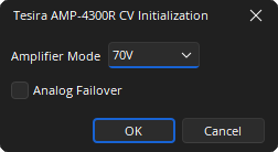
Amplifier Mode: A drop-down allows selection of the constant voltage mode, 70V and 100V, Constant voltage amplifiers do not support channel bridging.
Analog Failover: Will configure the amplifier input card for failover.
Low Impedance Amplifiers
Low impedance amplifiers support bridging of the channels. Each channel pair can be bridged together using the checkbox.
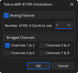
Analog Failover: Configures the amplifier input card for failover. If 8 channel amplifiers are used the additional EIC cards require specifying.
Bridged Channels: A tick box allows selection of the adjacent channels that are to be bridged.
DSP Block Representation
Tesira Amplifiers are represented on the layout as a single output block.
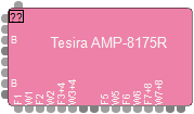
- The left side of the block has an active audio input port per audio channel available. Bridged outputs require a pair of amplified outputs and will therefore be represented with two ports on the block. The first (odd) numbered port of a bridged pair will be designated with a default port label of “B”, and the second (even) numbered port of the pair will be disabled. The DSP wiring must connect wires to the first port.
- The top of the block has one logic input port for power control.
- The bottom of the block has logic output ports for indicating faults and warnings from the amplified outputs (either as single channels or bridged channels, dependent on the block parameters).
See the Logic Charts page of System Control for more information.
Associating Analog Inputs
Add a four channel Analog Input block and set the equipment type to Amplifier. This will allow the analog audio from the amplifier to be streamed to a Tesira SERVER, SERVER I/O, or TesiraFORTÉ device for further processing.
A four channel or eight channel audio input block can be assigned to a four or eight channel Tesira Amplifier by setting the correct equipment type in the input Initialization Dialog.
Control Dialog
The amplifier dialog is configured to show channel and device indicators and controls for each enabled audio channel.
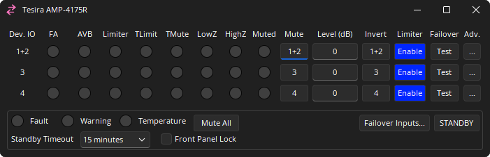
Channel Indicators and Controls
Dev. IO: Indicates which amplified output(s) are controlled by this channel of the block. For bridged channels, both output numbers are displayed. For non-bridged channels, only the single output number is displayed. Range of 1 - 8.
FA: When active, the channel is receiving its input from its failover analog input. It is only shown when analog failover is configured.
AVB: Lights to indicate that AVB audio is present:
- Off (grey): No AVB audio signal.
- Green: AVB Audio signal present.
- Yellow: AVB or failover audio is present and actively limiting.
- Red: AVB or failover audio is present and is being clipped.
Limiter:
- Off (grey): No Limiting of the audio signal.
- Yellow: Actively limiting.
- Red: Clipped audio.
TLimit: Audio limiting due to thermal over-temperature condition.
TMute: Audio muting due to thermal over-temperature condition.
LowZ: Low loudspeaker impedance detected.
HighZ: High loudspeaker impedance detected.
Muted: Indicated the current state of the amplifier channel:
- Off: Channel unmuted.
- Yellow: Channel unmuted. Chassis mute active.
- Red: Channel mute active.
Mute: Turns the channel output signal on/off.
Level: Adjusts the relative output volume. Range of -100 to 0.
Invert: Adjusts the polarity of the output signal. Range of 0° or 180°.
Enable Limiter: Will enable the amplifier Output limiter.
Failover: This column is only present when the amplifier has been configured for failover. Enabling test mode lights the button red and causes the amplifier to get its input from the channel’s analog failover input.
Adv.: Opens the Amplifier Advanced Dialog. Details below.
Device Indicators and Controls
Fault: Indicates when a frame fault is active.
Warning: Indicates when a frame warning is active.
Temperature: Indicates a frame level thermal fault.
- Off (grey): No fault.
- Yellow: Thermal warning.
- Red: Thermal fault.
Mute All: Mutes all channel on the Chassis.
Failover Inputs: Displays the failover Input dialog.
Standby: Toggles the amplifier between on and Standby.
Standby Timeout: The time before standby mode is enabled if signal falls below the standby threshold:
- Disabled (amplifier will not enter standby)
- 15 minutes
- 30 minutes
- 45 minutes
- 1 hour
Front Panel Lock: When selected the front panel channel selection controls will be locked.
Advanced Controls
For bridged outputs, a single set of channel indicators and attributes is displayed for both bridged amplifier outputs.
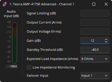
Audio Input: A meter showing the audio input level to the amplifier.
Signal Limiting: A read only attribute showing active output limiting.
Output Current (Amps): A read only attribute showing the expected Amps at the output.
Output Voltage (Vrms): A read only attribute showing the expected Voltage at the output.
Gain: Sets the gain, or sensitivity, of the amplifier. 0, 6, 12, 18 or 24dB (Default: 12dB)
Standby Threshold: Adjusts the threshold for standby timeout. Range of -100 to 0.
Expected Load Impedance: The expected output load impedance. Only shown for low impedance amplifier models. Range of 4 Ohms 8 Ohms.
Low Impedance Monitoring: When checked low impedance monitoring is enabled.
Failover Input: Only shown when analog failover is enabled. By default this is mapped to the same amplifier channel. If required the same failover channel can be mapped to multiple amplifier channels.
Failover Controls
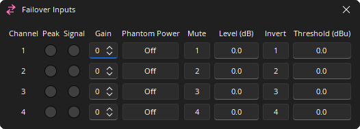
Channel: Represents the physical sequence of channels for failover. For 4 channel amplifiers they are mapped 1-4. For 8 channel amplifiers there are two EIC-4 cards and the channels are marked 1-8. The default mapping can be altered in the property sheet. Range of 1 - 8.
Peak: A software indicator that flashes when the input signal is within 3dB of clipping.
Signal: Lights to indicate that the analog signal is above the threshold setting.
Gain: Sets the amount of analog gain for that channel and is used to compensate for differing input levels (mic or line). Range of 0-66 in 6dB steps.
Phantom Power: Assigns +48 Volt phantom power to the input for use with condenser microphones.
Mute: Turns the input signal on/off.
Level: Adjusts the relative input volume. Range of -100 to +12.
Invert: Adjusts the polarity of the input signal. Range of 0° or 180°.
Threshold: Adjusts the threshold of the signal LED. -64 to +30.